Device utilizing single camera for achieving binocular vision three-dimensional imaging

A binocular vision, three-dimensional imaging technology, applied in the direction of using optical devices, measuring devices, photography, etc., can solve the problems of low resolution, difficult calibration, low calibration accuracy, etc., to achieve high depth resolution, reduce camera Internal reference, the effect of reducing difficulty

Inactive Publication Date: 2015-03-25
SUZHOU JIANGAO OPTOELECTRONICS TECH
View PDF7 Cites 9 Cited by
  • Summary
  • Abstract
  • Description
  • Claims
  • Application Information

AI Technical Summary

Problems solved by technology

However, due to various reasons, the internal parameters of the two cameras cannot be exactly the same. In addition to the external parameters, there are as many as 14 parameters that need to be calibrated, so the calibration is difficult and the calibration accuracy is not high. The reconstruction effect has a greater impact
In addition, after the two cameras are fixed, the imaging depth resolution is inversely related to the distance of the object. The farther the object is, the smaller the parallax is and the lower the resolution is. Therefore, it is impossible to achieve higher accuracy for the entire object for objects with greater depth.

Method used


Image

  • Device utilizing single camera for achieving binocular vision three-dimensional imaging

Examples


Embodiment Construction

[0016] The present invention will be specifically introduced below in conjunction with the accompanying drawings and specific embodiments.

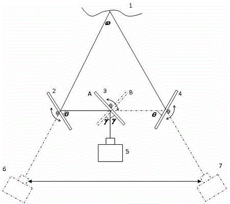
[0017] A device for realizing binocular three-dimensional imaging by using a single camera 5, comprising: a camera 5 placed behind an object 1 to be measured, reflecting the left view image 6 of the object to the left view image 6 of the camera 5, and reflecting the object's The right view image 7 is reflected to the right view image 7 reflection assembly of the single camera 5 .

[0018] The left-view image 6 reflection assembly includes: a middle vibrating mirror 3, a left vibrating mirror 2 that receives light reflected by the middle vibrating mirror 3, and a motor that drives the middle vibrating mirror 3 and the left vibrating mirror 2 to rotate to an appropriate position. The right-view image 7 reflection assembly includes: a middle vibrating mirror 3, a right vibrating mirror 4 that receives light reflected by the middle vibrating ...


PUM


Abstract

The invention discloses a device utilizing a single camera for achieving binocular vision three-dimensional imaging. The device comprises the camera arranged behind an object to be measured, a left view image reflecting module for reflecting a left view image of the object to the camera, and a right view image reflecting module for reflecting a right view image of the object to the single camera. The single camera is utilized for replacing two cameras in a traditional method, a system is simplified, camera internal parameters to be calibrated are reduced, and the difficulty of system calibration is lowered; in addition, in binocular vision, the positive correlation between the depth resolution of three-dimensional imaging and the distance of the two cameras is formed, the inverse correlation is formed between the depth resolution of three-dimensional imaging and the distance from the object to the camera is formed, three galvanometers can rotate around the axis, and therefore the system can obtain the high depth resolution for objects of different depths.

Description

technical field [0001] A three-dimensional imaging device, in particular a binocular vision three-dimensional imaging device. Background technique [0002] 3D imaging plays an important role in industrial inspection, profiling, machine vision, artificial intelligence and other fields. The current three-dimensional imaging method is mainly a non-contact photoelectric detection method, and the binocular vision method is widely used because of its simple structure and low cost. [0003] The traditional binocular vision 3D imaging device generally includes two left and right cameras. After the two cameras are binocularly calibrated, the calibrated and calibrated left and right views can be obtained. The matching algorithm is used to obtain the disparity map. The internal and external parameters of the object can be used to reconstruct the three-dimensional model of the object. However, due to various reasons, the internal parameters of the two cameras cannot be exactly the sam...

Claims


Application Information

Patent Timeline
Patent Type & Authority Applications(China)
IPC IPC(8): G03B35/18G02B27/22G01B11/24
CPCG03B35/18G01B11/24
Inventor 林斌俞宝清张汝婷
Owner SUZHOU JIANGAO OPTOELECTRONICS TECH
Why Eureka
Try Eureka