Wireless charging coil manufacturing method and wireless charging structure

A technology of wireless charging and manufacturing method, applied in coil manufacturing, coil, battery circuit devices, etc., can solve the problems of complex plastic parts manufacturing, high cost of wireless charging structure, large charging gap, etc., to facilitate industrialization and popularization, and improve area utilization. rate, a wide range of effects

Active Publication Date: 2015-03-25
GUANGDONG JANUS SMART GRP CO LTD
View PDF6 Cites 27 Cited by
  • Summary
  • Abstract
  • Description
  • Claims
  • Application Information

AI Technical Summary

Problems solved by technology

The charging structure obtained in this way will increase the thickness of the whole machine, which cannot meet the requirements of the development of light and thin equipment.
Moreover, when used for a long time, the wireless charging coil will fall off from the casing or be partially degummed, resulting in poor reliability.
The most important thing is that the general wireless charging coil is pasted in the casing, so that the receiving coil and the transmitting coil are separated by at least two layers of the thickness of the device casing, resulting in a large charging gap and a decrease in charging efficiency
At present, there are also proposals for direct molding on the shell, but they rely on special composite metal-plastic materials, which makes the production of plastic parts more complicated, and the cost of the final wireless charging structure is also higher.

Method used


Image

  • Wireless charging coil manufacturing method and wireless charging structure
  • Wireless charging coil manufacturing method and wireless charging structure
  • Wireless charging coil manufacturing method and wireless charging structure

Examples


Embodiment Construction

[0014] The present invention will be described in further detail below in combination with specific embodiments and with reference to the accompanying drawings.

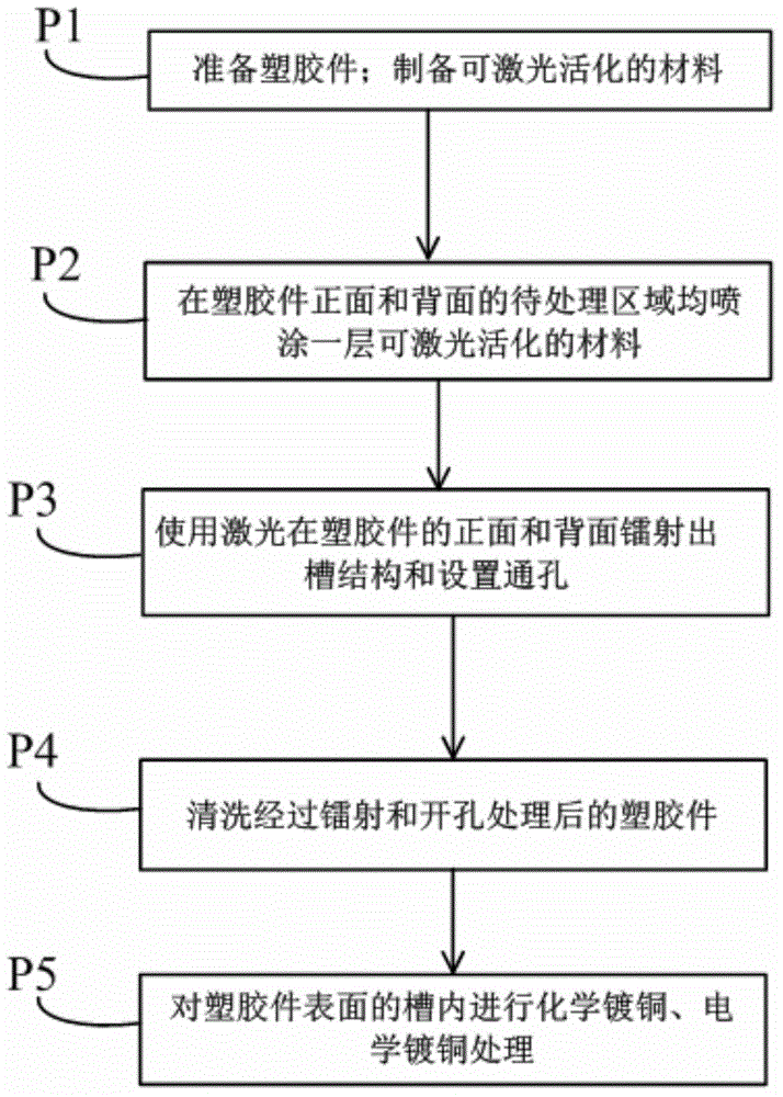
[0015] Such as figure 1 As shown, it is a flow chart of the manufacturing method of the wireless charging coil in this specific embodiment, including the following steps:

[0016] P1) Prepare plastic parts; prepare laser-activatable coatings.

[0017] In this step, the plastic parts are common plastic parts already on the market, and composite plastic materials prepared by special processes are not required, and no additional materials, such as non-metallic light-induced catalysts, etc., need to be added to common plastic materials. Generally, composite plastic materials prepared by special processes need to undergo secondary molding, and the process is more complicated. Moreover, secondary molding also leads to thicker composite plastic materials, which is not convenient for the development of lighter and thinner ...


PUM


Abstract

The invention discloses a wireless charging coil manufacturing method. The wireless charging coil manufacturing method comprises the following steps that (1), a plastic part is prepared, and laser-activated coatings are prepared; (2), to-be-processed areas of the obverse side and the reverse side of the plastic part are each coated with one layer of laser-activated coating; (3), a spiral coil slot and feed point slots are formed in the obverse side of the plastic part through laser, through holes are formed in an internal end point and the second feed point slot, and a pattern slot is formed in the reverse side of the plastic part through laser; (4), the plastic part processed in the third step is washed; (5), chemical copper plating and electrical copper plating are sequentially formed in the slots in the surfaces of the plastic part. A wireless charging structure comprises the plastic part, coil patterns, the two feed points and conducting wire patterns, wherein the coil patterns, the two feed points and the conducting wire patterns are directly formed on the plastic part through the wireless charging coil manufacturing method. The wireless charging coil manufacturing method and the wireless charging structure can meet the development requirements of lightness, thinness and reliability of electronic equipment, the manufacturing process is simple, and the cost of manufactured products is low.

Description

【Technical field】 [0001] The invention relates to a manufacturing method of a wireless charging coil and a wireless charging structure. 【Background technique】 [0002] Electromagnetic induction type (use current to generate magnetic field through coil to realize near-field wireless power supply), magnetic field resonance type (use magnetic coupling resonance effect to realize near-field wireless power supply), and radio wave radiation type (electric energy is converted into radio waves to transmit power through radiation) are the most widely used. Three wireless charging technologies. Among them, the key points in the electromagnetic induction wireless charging technology are the shape of the transmitting coil and the receiving coil, the design of the installation position and parameters. At present, most receiving coils are made of copper wires, or are made of FPC flexible printed boards. The finished copper coil is used as a separate physical module, and then installed o...

Claims


Application Information

Patent Timeline
Patent Type & Authority Applications(China)
IPC IPC(8): H01F41/04H01F5/00H02J7/00H02J17/00H02J50/10
Inventor 贾智亚
Owner GUANGDONG JANUS SMART GRP CO LTD
Why Eureka
Try Eureka