Eureka AIR delivers breakthrough ideas for toughest innovation challenges, trusted by R&D personnel around the world.

Self-guided unidirectional edge state transport method in magnetic photonic crystals based on surface modification

A magnetic photonic crystal and surface modification technology, which is applied to waveguides, waveguide-type devices, circuits, etc., can solve the problems of electromagnetic wave loss, unsuitable integration, and increased production costs, and achieve the effects of easy processing, low cost, and simple structure

Active Publication Date: 2017-06-06
HUAIYIN TEACHERS COLLEGE
View PDF4 Cites 0 Cited by
  • Summary
  • Abstract
  • Description
  • Claims
  • Application Information

AI Technical Summary

Problems solved by technology

In the above method, after introducing dielectric photonic crystals such as alumina, a new photonic crystal structure is added, which makes the overall structure complex and is not suitable for integration
When restrictive layers such as metal baffles are introduced to suppress the space radiation of electromagnetic waves, electromagnetic waves will be lost due to the strong absorption of metals.
Through the zigzag self-guiding boundary mode of the graphene-like structure, there are more cylinders per unit area, which increases the production cost and the arrangement is more complicated.

Method used


Image

  • Self-guided unidirectional edge state transport method in magnetic photonic crystals based on surface modification
  • Self-guided unidirectional edge state transport method in magnetic photonic crystals based on surface modification
  • Self-guided unidirectional edge state transport method in magnetic photonic crystals based on surface modification

Examples


Embodiment Construction

[0037] Below in conjunction with accompanying drawing and specific embodiment, further illustrate the present invention, should be understood that these embodiments are only for illustrating the present invention and are not intended to limit the scope of the present invention, after having read the present invention, those skilled in the art will understand various aspects of the present invention Modifications in equivalent forms all fall within the scope defined by the appended claims of this application.

[0038] This application is supported by the open project of Huai'an Key Laboratory of Information Functional Materials Research, the Jiangsu Provincial Natural Science Foundation (BK20130854), the National 2014 University Student Innovation and Entrepreneurship Training Program (Project Approval No.: 201410323018) and the 2014 Jiangsu University Student Practice Innovation Supported by the training plan project (project approval number: 201410323018Z).

[0039] The prese...


PUM


Abstract

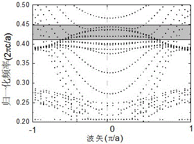
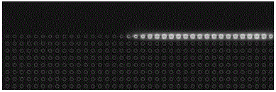
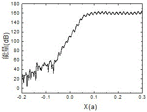
The invention discloses a magnetic photonic crystal self-conductance unidirectional edge state transmission method based on surface finish. The method comprises the steps of establishing a magnetic photonic crystal, wherein the magnetic photonic crystal comprises a base material provided with through holes and multiple ferrite posts arranged in the through holes; applying an additional bias magnetic field to the ferrite posts so as to open an energy band Dirac degeneracy point and generate a band gap capable of simulating the integer quantum hall effect; increasing the duty ratio and reducing the frequency of the band gap of the photonic crystal by increasing the cross sectional area of each ferrite post or reducing the lattice constant if the band gap is located at the position where normalized frequency is over 0.5; introducing surface defects by changing the sizes of the ferrite posts on the boundary to enable the projection energy band of the magnetic photonic crystal to be in the unidirectional boundary state, so that self-conductance unidirectional edge transmission of energy is achieved. By the adoption of the method, stable unidirectional transmission of electromagnetic beams is achieved, and the unidirectional transmission characteristic can not be changed when certain ferrite posts on the boundary are removed or metal is inserted into the boundary.

Description

technical field [0001] The invention relates to the technical field of electromagnetic beam control, in particular to a method for realizing unidirectional transmission of electromagnetic beams by using an adjustable gyromagnetic medium (magnetic photonic crystal based on ferrite), specifically a magnetic photonic crystal self-guiding single The method for transporting to the edge state is more specifically a self-guided one-way edge state transport method based on the surface modification of the magnetic photonic crystal. Background technique [0002] Ferrite material is the main medium that constitutes the electromagnetic unidirectional edge state at this stage. By analogy, the integer quantum Hall effect can be compared, the introduction of dielectric photonic crystals such as alumina, metal baffles and other confinement layers to suppress the space radiation of electromagnetic waves, or through the zigzag self-guided boundary mode of the graphene-like structure, the elec...

Claims


Application Information

Patent Timeline
Patent Type & Authority Patents(China)
IPC IPC(8): H01P3/16
Inventor 李清波周平孙慧玲平学伟李珊珊
Owner HUAIYIN TEACHERS COLLEGE
Why Eureka
Eureka Blog
Learn More