Power supply-capacitor series connection type DC converter

A technology of DC converters and capacitors connected in series, which is applied in the direction of converting DC power input to DC power output, high-efficiency power electronic conversion, and adjusting electrical variables. It can solve the problems of high switching loss and high cost, reduce voltage stress, and solve inefficient effect

Active Publication Date: 2015-03-25
SHANDONG UNIV
View PDF4 Cites 7 Cited by
  • Summary
  • Abstract
  • Description
  • Claims
  • Application Information

AI Technical Summary

Problems solved by technology

In the DC boost circuit, the voltage stress of the switch tube and the freewheeling diode is the bus voltage value, resulting in high switching loss; and when designing the DC boost circuit, the hardware engineer must choose a switch tube and a switch with a withstand voltage higher than the bus voltage value. Diodes are expensive

Method used


Image

  • Power supply-capacitor series connection type DC converter
  • Power supply-capacitor series connection type DC converter
  • Power supply-capacitor series connection type DC converter

Examples


Embodiment Construction

[0031] In the following, the present invention will be further described in conjunction with the accompanying drawings and examples. Firstly, the structure and working principle of the power supply-capacitor series basic DC converter unit of the present invention will be described.

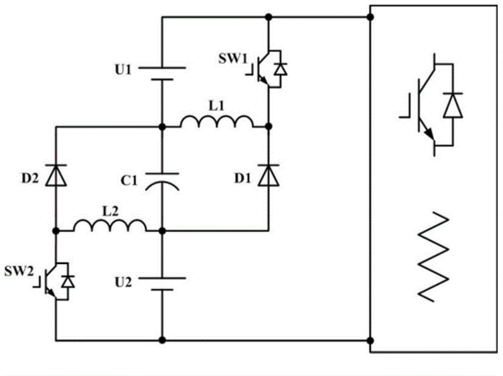
[0032] The topology of the basic DC converter unit of the present invention is as figure 1 As shown, it includes: a DC power supply U1, a capacitor C1, and a DC power supply U2 are sequentially connected in series, and a post-stage circuit is connected in series between the positive pole of the DC power supply U1 and the negative pole of the DC power supply U2;

[0033] The two ends of the DC power supply U1 are connected in parallel with a switch tube SW1 and a series circuit of the inductor L1; the connection point of the switch tube SW1 and the inductor L1 is connected to the cathode of the diode D1, and the anode of the diode D1 is connected to the negative pole of the capacitor C1;

[0034] A...


PUM


Abstract

The invention discloses a power supply-capacitor series connection type DC converter which is formed by connecting multiple power supply-capacitor series connection type basic DC converter units in series. Each power supply-capacitor series connection type basic DC converter unit comprises a DC power supply U1, a capacitor C1 and a DC power supply U2, wherein the DC power supply U1, the capacitor C1 and the DC power supply U2 are connected in series in sequence, and a post-stage circuit is connected between the positive electrode of the DC power supply U1 and the negative electrode of the DC power supply U2 in series. The two ends of each DC power supply U1 are connected with a series circuit of a switch tube SW1 and an electrical inductor L1 in parallel. The connection points of the switch tubes SW1 and the electrical inductors L1 are connected with the negative electrodes of diodes D1, and the positive electrodes of the diodes D1 are connected to the negative electrodes of capacitors C1. The two ends of each DC power supply U2 are connected with a series circuit of a switch tube SW2 and an electrical inductor L2 in parallel. The connection points of the switch tubes SW2 and the electrical inductors L2 are connected with the positive electrodes of diodes D2, and the negative electrodes of the diodes D2 are connected to the positive electrodes of the capacitors C1.

Description

technical field [0001] The invention relates to a DC converter, in particular to a power supply-capacitor series DC converter. technical background [0002] Since the 21st century, with the continuous consumption of fossil energy, human society is facing an unprecedented energy crisis. The utilization of renewable energy is gradually attracting the attention of various countries, and photovoltaic grid-connected inverter technology, as an important form of renewable energy utilization, has been more in-depth research. [0003] The energy conversion efficiency and MPPT (Maximum Power Point Tracking) efficiency of photovoltaic inverters directly measure the performance of photovoltaic inverters. A high energy conversion rate means that more renewable energy has been effectively used, bringing The lower operating temperature of the inverter is achieved, thereby greatly reducing the size of the radiator, greatly reducing the weight and saving costs. [0004] The currently widel...

Claims


Application Information

Patent Timeline
Patent Type & Authority Applications(China)
IPC IPC(8): H02M3/155
CPCH02M3/155H02M1/0048Y02B70/10
Inventor 高峰陈梦星
Owner SHANDONG UNIV
Why Eureka
Try Eureka