
Mixer circuit for power line carrier modulation and demodulation and demodulation module

A power line carrier modulation and demodulation technology, applied in the field of communication, can solve the problems of reducing the receiving sensitivity of the power line carrier modulation and demodulation system, affecting the noise performance of the power line carrier modulation and demodulation system, and the linearity is not very high, so as to reduce noise and improve Linearity, the effect of overcoming switching stage noise

Inactive Publication Date: 2015-03-25
SHENZHEN KAIRUI INFORMATION ENG CO LTD
View PDF3 Cites 0 Cited by
  • Summary
  • Abstract
  • Description
  • Claims
  • Application Information

AI Technical Summary

Problems solved by technology

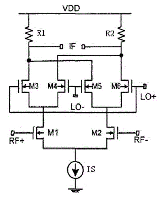
[0004] like figure 1 The biggest advantage of the mixer is that it has a high conversion gain, but it also has some inherent defects, such as relatively poor noise, and the linearity is not very high
If the noise of the mixer is too large, it will seriously affect the noise performance of the power line carrier modulation and demodulation system, thereby reducing the receiving sensitivity of the power line carrier modulation and demodulation system

Method used


Image

  • Mixer circuit for power line carrier modulation and demodulation and demodulation module
  • Mixer circuit for power line carrier modulation and demodulation and demodulation module
  • Mixer circuit for power line carrier modulation and demodulation and demodulation module

Examples


Embodiment Construction

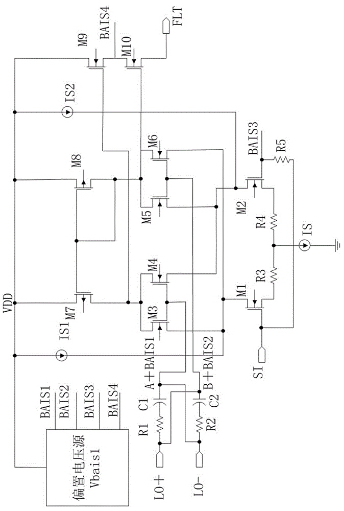
[0018] The structure of the mixer circuit proposed by the present invention is as follows: figure 2 As shown, the first MOS transistor M1, the second MOS transistor M2, the third MOS transistor M3, the fourth MOS transistor M4, the fifth MOS transistor M5, the sixth MOS transistor M6, the seventh MOS transistor M7, and the eighth MOS transistor M8, the ninth MOS transistor M9 and the tenth MOS transistor M10, the current source IS, the first current source IS1 and the second current source IS2, and the bias voltage source Vbias1. And the first MOS transistor M1, the second MOS transistor M2, the third MOS transistor M3, the fourth MOS transistor M4, the fifth MOS transistor M5, the sixth MOS transistor M6, the ninth MOS transistor M9 and the tenth MOS transistor M10 are NMOS transistors tube; the seventh MOS tube M7 and the eighth MOS tube M8 are PMOS tubes. The connection relationship is: the analog signal SI coupled in by the power line is input from the gates of the first...


PUM


Abstract

The invention discloses a mixer circuit for power line carrier modulation and demodulation. The mixer circuit consists of a first MOS (Metal Oxide Semiconductor) tube M1, a second MOS tube M2, a third MOS tube M3, a fourth MOS tube M4, a fifth MOS tube M5, a sixth MOS tube M6, a seventh MOS tube M7, an eighth MOS tube M8, a ninth MOS tube M9, a tenth MOS tube M10, a current source IS, a first current source IS1, a second current source IS2 and a bias voltage source Vbias1. On the basis of a conventional Gilbert mixer circuit, the current sources are introduced into a switching tube, so that the noise is lowered while a conversion gain index is not deteriorated.

Description

technical field [0001] The invention belongs to the technical field of communication, and mainly relates to a frequency mixing circuit compatible with a standard CMOS process and used for the front end of a power line carrier modulation and demodulation system. Background technique [0002] Power line communication (Power Line Communication, PLC) is to use the existing almost ubiquitous power line as a communication carrier, and realize the transmission of information on the existing power line without rewiring. This technology is to load the high-frequency signal carrying information on the power line, and then use the power line to transmit, and the modem receiving the information separates the signal from the messy information to realize the transmission of information. In the power line carrier modulation and demodulation system, the mixer is a very critical core circuit module. Its process compatibility, its noise, linearity, conversion gain and other performance indica...

Claims


Application Information

Patent Timeline
Patent Type & Authority Applications(China)
IPC IPC(8): H03D7/12H04B3/54
Inventor 王建安
Owner SHENZHEN KAIRUI INFORMATION ENG CO LTD
Learn More