LED driving circuit

A technology of LED drive and drive circuit, applied in the direction of lamp circuit layout, electric light source, lighting device, etc., can solve the problems of flickering, impractical feasibility, dimming of output light, etc., and achieve the effect of improving input response speed

Active Publication Date: 2015-03-25
SHANGHAI BRIGHT POWER SEMICONDUCTOR CO LTD
View PDF4 Cites 8 Cited by
  • Summary
  • Abstract
  • Description
  • Claims
  • Application Information

AI Technical Summary

Problems solved by technology

At present, some linear chips have added over-power and over-temperature protection. The principle is to protect the chip by reducing the output current of the LED, which also causes the output light to dim or flicker.
So this simple linear drive method is not practical

Method used


Image

  • LED driving circuit
  • LED driving circuit
  • LED driving circuit

Examples


Embodiment Construction

[0018] The specific embodiment of the present invention will be further described in detail below in conjunction with the accompanying drawings.

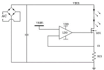
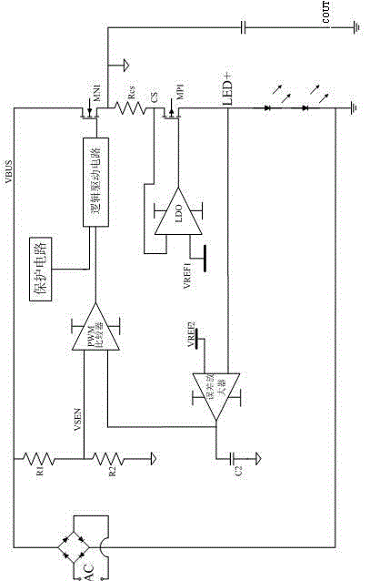
[0019] The LED driving circuit of the present invention includes an AC input stage, an output terminal, an output voltage feedback terminal, a control loop for controlling the duty cycle of the power tube switch according to the output voltage feedback terminal, and a power tube connected to the control loop;

[0020] It also includes a first reference voltage, an LDO, and an adjustment transistor connected between the power transistor and the load LED, the control end of the adjustment transistor is connected to the output end of the LDO, and the two input ends of the LDO are respectively connected to the adjustment transistor and the CS sampling The common terminal of the resistor RCS and the first reference voltage; also includes an output capacitor connected to the output terminal, and the common terminal of the adjusting tube an...


PUM


Abstract

The invention provides an LED driving circuit which comprises an alternating-current input stage, an output end, an output voltage feedback end, a control loop, a power tube, first reference voltage, an LDO and an adjusting tube. The control loop controls the on-off duty ratio of the power tube according to the output voltage feedback end. The power tube is connected with the control loop. The adjusting tube is connected between the power tube and a load LED. Two input ends of the LDO are connected with a public end of the adjusting tube and the load LED, and the first reference voltage respectively. The LED driving circuit further comprises an output capacitor connected with the output end. The public end of the adjusting tube and the load LED serves as the output voltage feedback end. The control loop comprises an alternating-current sampling circuit. A switched capacitor circuit and the linear constant-current LDO are combined so that the LDO can achieve ripple-wave-free constant currents for the LED and feed back the output voltage to the switched capacitor circuit, energy can be transmitted according to needs, direct sampling of input voltage is achieved by adopting the alternating-current sampling circuit, and the input response speed is increased.

Description

technical field [0001] The invention belongs to the field of integrated circuit design and relates to a switching power supply, in particular to an LED driving circuit. Background technique [0002] With the development of high-voltage LED lamp beads and the increasingly stringent requirements for cost and volume of LED drive power supplies, the low-cost high-voltage constant-current linear drive method has achieved certain technical updates and applications in the past few years. However, the current linear drive method always has low reliability, requires high matching of input voltage and output lamp beads, and cannot withstand large fluctuations in input and output voltages, which hinders the linear drive method from being used in mass production and safety applications of LED lighting. middle. [0003] figure 1 The common flicker-free linear drive methods currently on the market are given. 20 is a constant current linear driver chip, the power supply of the chip is p...

Claims


Application Information

Patent Timeline
Patent Type & Authority Applications(China)
IPC IPC(8): H05B37/02
Inventor 易坤赵方麟陈雪松
Owner SHANGHAI BRIGHT POWER SEMICONDUCTOR CO LTD
Why Eureka
Try Eureka