Check patentability & draft patents in minutes with Patsnap Eureka AI!

Control device and control method for hybrid vehicle power unit

A hybrid vehicle and power unit technology, applied in the direction of hybrid vehicles, power devices, air pressure power devices, etc., can solve the problems of vehicle power performance reduction, limited output, etc., to achieve suppression reduction, prevent demagnetization, and suppress total output Effect

Inactive Publication Date: 2015-03-25
TOYOTA JIDOSHA KK
View PDF1 Cites 0 Cited by
  • Summary
  • Abstract
  • Description
  • Claims
  • Application Information

AI Technical Summary

Problems solved by technology

[0006] Reduced electrical performance of vehicles when the output of rotating electrical machines is limited to prevent demagnetization of permanent magnets
Specifically, when suppressing the amount of rare earth metals added to increase the coercive force, it is necessary to further limit the output

Method used


Image

  • Control device and control method for hybrid vehicle power unit
  • Control device and control method for hybrid vehicle power unit
  • Control device and control method for hybrid vehicle power unit

Examples


Embodiment Construction

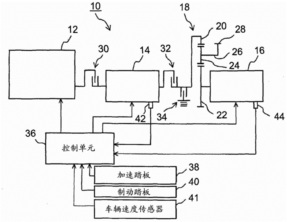
[0017] Hereinafter, embodiments of the present invention will be described with reference to the accompanying drawings. figure 1 is a block diagram showing a schematic configuration of a power unit 10 for a hybrid vehicle. The power unit 10 includes three prime movers. One prime mover is the internal combustion engine 12 and the remaining two prime movers are rotating electric machines 14 , 16 . Internal combustion engine 12 may be, for example, an Otto cycle engine or a diesel engine. In the present embodiment, the two rotating electrical machines are both permanent magnet type rotating electrical machines using permanent magnets as field magnets, and specifically both may be permanent magnet type synchronous machines.

[0018] Two rotary electric machines are respectively connected to two elements among the three elements of the planetary gear mechanism 18 , and the other element is connected to a driving wheel. In the present embodiment, the rotary electric machine 14 is...


PUM


Abstract

A power unit includes a first rotating electrical machine and a second rotating electrical machine as prime movers. The first rotating electrical machine, the second rotating electrical machine and a drive wheel are respectively connected to a ring gear (R), sun gear (S) and carrier (C) of a planetary gear mechanism. When a temperature of a permanent magnet of the first rotating electrical machine becomes close to a temperature at which demagnetization occurs, an output of the first rotating electrical machine is reduced (from R1 to R2), and an output of the second rotating electrical machine is increased (from S1 to S3). Thus, the total output (CI) of the power unit is kept.

Description

technical field [0001] The present invention relates to the control of a hybrid vehicle power unit comprising multiple types of prime movers, including a rotating electrical machine. Background technique [0002] A hybrid vehicle comprising an internal combustion engine and a rotating electric machine as drive prime movers is well known. In this specification, "rotating electric machine" is used as a general term for an electrical device that functions as a motor, a generator, or both. A rotating electrical machine using a permanent magnet (permanent magnet type rotating electrical machine) is widely used as a rotating electrical machine used as a prime mover of a vehicle because of its small size and high power characteristics. [0003] The permanent magnets may be demagnetized, ie the magnetic flux density of the permanent magnets may decrease. Temperature and external magnetic fields are believed to be the cause of demagnetization. When an opposite external magnetic fi...

Claims


Application Information

Patent Timeline
Patent Type & Authority Applications(China)
IPC IPC(8): B60K6/445B60W20/00B60W10/08B60L50/16
CPCB60K6/445B60W10/08B60W2510/087B60W2710/083B60W20/50Y02T10/62Y02T10/72H02P5/695
Inventor 宫本知彦池本正幸仓本守八木教行
Owner TOYOTA JIDOSHA KK
Features
  • R&D
  • Intellectual Property
  • Life Sciences
  • Materials
  • Tech Scout
  • Unparalleled Data Quality
  • Higher Quality Content
  • 60% Fewer Hallucinations
Learn More