Spiral slideway infrared corncob drying machine

A technology of spiral slide and corn ear, which is applied in the field of agricultural engineering, can solve the problems of corn kernels bursting and high energy consumption, and achieve the effects of reducing obstruction, low energy consumption and improving uniformity.

Inactive Publication Date: 2015-04-01
SHANDONG UNIV OF TECH
View PDF14 Cites 6 Cited by
  • Summary
  • Abstract
  • Description
  • Claims
  • Application Information

AI Technical Summary

Problems solved by technology

The corn cob dryers involved in the above patents all adopt hot air convection drying, which consumes relatively high energy consumption and sometimes causes corn kernels to burst. After changing to infrared radiation drying, a national invention patent was applied for, and the patent number is: ZL201310056847.7 ; After changing to a rotatable shifting rod to make the feeding trough convenient to support, a national invention patent was applied for, the application number is: 201310060839.X; after the limit sleeve was added, a national invention patent was applied again, the patent number is : ZL201310065945.7; After adding the toggle wheel or toggle mechanism, the national invention patent was applied for, the application numbers are: 201410060366.8 and 201410110342.9; after the toggle lever was changed to a straight rod, the national invention patent was applied again, the application number For: 201410227754.0
However, the infrared corn ear dryers involved in the above-mentioned patents all need to be equipped with a conveying device so that the corn ears can absorb heat evenly and dry during the movement.

Method used


Image

  • Spiral slideway infrared corncob drying machine
  • Spiral slideway infrared corncob drying machine
  • Spiral slideway infrared corncob drying machine

Examples


Embodiment Construction

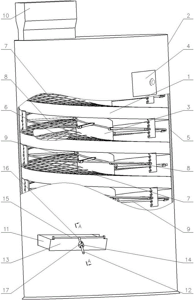
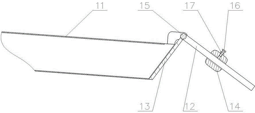
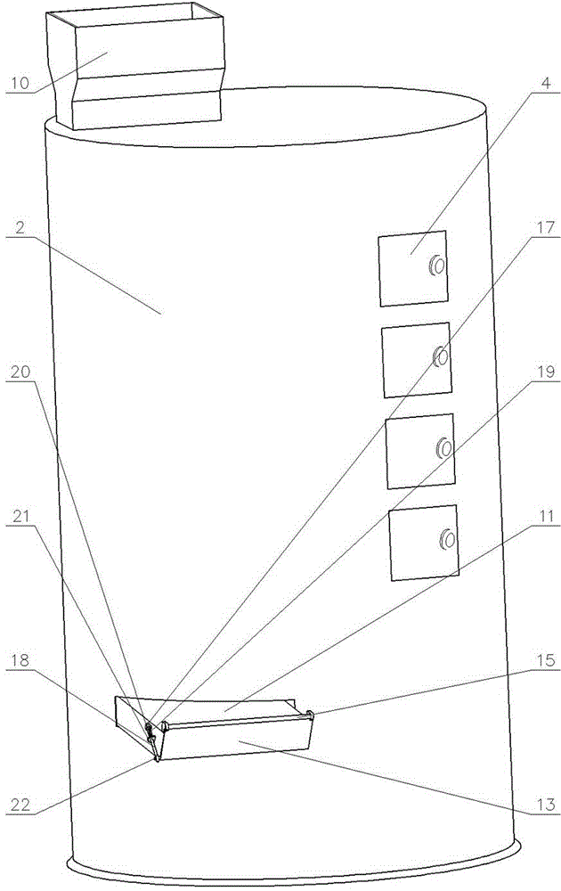
[0016] 1. Spiral slideway 2, box wall 3, central pipe 4, observation door 5, insulation layer 6, pattern 7, shield 8, radiation frame 9, radiation element 10, material inlet 11, material outlet 12, adjustment rod 13. Baffle plate 14, adjustment block 15, pin shaft I 16, screw 17, nut 18, pull rod 19, spring 20, spring seat 21, lug 22, pin shaft II.

[0017] exist Figure 1~2In the shown embodiment: the outer cylindrical surface of the cylindrical box wall 2 with the axis vertically arranged is provided with a plurality of observation doors 4, the inner surface of the box wall 2 is provided with an insulating layer 5, and the inner surface of the box wall 2 is along the axis of the cylinder. A spiral slideway 1 is provided, and the inner edge of the spiral slideway 1 is supported on the central tube 3 whose axis is coaxial with the box wall 2; the radial width of the spiral slideway 1 along the box wall 2 is greater than the maximum length of the ear of corn. The upper surface...


PUM


Abstract

The invention provides a spiral slideway infrared corncob drying machine which is characterized in that: the box wall internal surface is provided with a spiral slideway with concave and convex patterns, a mesh protection cover is arranged above the upper surface of a spiral slideway and along the spiral slideway, a radiation device with adjustable height is arranged at a position above the mesh protection cover near the lower surface o the spiral slideway and along the spiral slideway, the top of the box body is provided with a feed inlet located at the start end of the spiral slideway, the bottom of the box body is provided with a material outlet located at the terminalend of the spiral slideway, the material outlet is provided with a speed control device, both ends of a pin shaft I which is at the middle part of the speed control device and is fixedly connected with the a baffle are supported on two side walls, the center of the length direction of the pin shaft I is provided with an adjusting rod stretching out along the direction vertical to the axis of the pin shaft I, an adjusting block provided with a light hole sleeves the adjusting rod by the light hole, and an extension-in end of a screw with a nut is then screwed in a threaded hole orthogonal to the axis of the light hole. The spiral slideway infrared corncob drying machine has the advantages of high drying efficiency, low energy consumption, simple structure and reliable work.

Description

technical field [0001] The invention provides a spiral slideway infrared corn ear dryer, which belongs to the technical field of agricultural engineering and is mainly used for drying wet corn ears after picking. Background technique [0002] China is a large agricultural country, especially in Shandong, Henan and Northeast China, which are the major food producing areas such as corn. With the development of the breeding industry and the increase in the demand for feed, the planting area of ​​corn has gradually expanded, and the output has increased year by year. The harvest moisture of corn is generally 30%~35%. If there is no good corn drying equipment, it will cause a lot of loss due to excessive moisture and mold. Therefore, farmers' demand for corn dryers is becoming more and more urgent. It is of great significance to develop corn dryers with high precipitation, good drying uniformity and high quality to promote the development of corn industry. [0003] At present, ...

Claims


Application Information

Patent Timeline
Patent Type & Authority Applications(China)
IPC IPC(8): A23B9/08
CPCY02P60/85
Inventor 王相友魏忠彩孙传祝彭丽芳卢延芳李学强
Owner SHANDONG UNIV OF TECH
Why Eureka
Try Eureka