Novel pipeline gas-liquid separator

A technology of liquid separator and pipeline gas, applied in the field of pipeline gas-liquid separator, can solve the problems of complex structure, low separation efficiency, large volume of natural gas gas-liquid separator, etc. Effect of gas-liquid contact area

Inactive Publication Date: 2015-04-01
CHINA UNIV OF PETROLEUM (EAST CHINA)
View PDF0 Cites 13 Cited by
  • Summary
  • Abstract
  • Description
  • Claims
  • Application Information

AI Technical Summary

Problems solved by technology

[0003] In order to solve the problems of large volume, complex structure and low separation efficiency of the natural gas gas-liquid separator, the present invention provides a new type of pipeline gas-liquid separator, which puts the centrifugal separation part and the mechanical collection part in the pipeline together , which greatly reduces the volume of separation equipment, improves the collection efficiency, and is suitable for gas-liquid separation in natural gas pipelines

Method used


Image

  • Novel pipeline gas-liquid separator
  • Novel pipeline gas-liquid separator
  • Novel pipeline gas-liquid separator

Examples


Embodiment

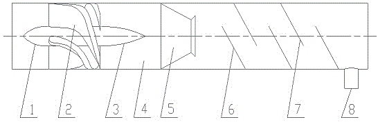
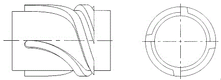
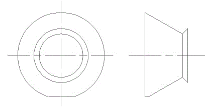
[0018] like figure 1 , figure 2 , image 3 , Figure 4 , Figure 5 and Image 6 As shown, the novel pipeline gas-liquid separator of the present invention includes a hydrocyclone separation component and a mechanical trapping component arranged in the pipeline. The hydrocyclone separation components include a steady flow spinner, a separation cylinder (4) and a separation cone (5), and the steady flow spinner consists of a guide (1), a guide vane (2) and a steady flow cone (3); The mechanical trapping parts include front bow-shaped plates (6) and rear bow-shaped plates (7) which are staggered and inclined. Elongated grooves (9) are provided. In this embodiment, the total number of bow-shaped plates is preferably 5. The slotting directions of the front and rear bow-shaped plates are staggered, and the stagger angle is 45-90°, preferably 90° in this embodiment. A liquid collecting pipe (8) is arranged on the pipeline behind the arcuate plate.

[0019] When in use, the li...


PUM


Abstract

The invention discloses a novel pipeline gas-liquid separator. The separator is composed of a process pipeline as well as a fluid-stabilizing component, a swirling component, a separating component and a capturing component which are arranged in the pipeline, wherein the fluid-stabilizing component comprises a guider arranged at the front end of a guide blade and a fluid-stabilizing cone arranged at the rear end, and plays a role of stabilizing a fluid; the swirling component is a guide blade concentric with the pipeline, and forces the fluid to generate a centrifuging action; the separating component comprises a separating barrel body in a straight pipe section and a porous medium separating cone in a conical section, and can be used for achieving gas-liquid centrifuging separation; the capturing component comprises a front arch-shaped plate, a rear arch-shaped plate and a liquid-collecting tube arranged behind the arch-shaped plates, and can be used for achieving capturing of liquid drops; long-strip-shaped grooves are formed in the arch-shaped plates, the grooving directions in the front arch-shaped plate and the rear arch-shaped plate are staggered, and liquid-flowing grooves are formed in the lower part of the separating cone and the bottoms of the arch-shaped plates. Through the technical scheme, according to the pipeline gas-liquid separator disclosed by the invention, the centrifuging separation component and the mechanical capturing component are arranged in the pipeline, and thus the size of the separator is greatly reduced and the capturing efficiency is increased. Meanwhile, due to the staggered arrangement of the arch-shaped plates, the movement path of the fluid is lengthened, and the capturing probability of the liquid is increased.

Description

technical field [0001] The invention relates to a gas-liquid separator, in particular to a pipeline gas-liquid separator combined with centrifugal separation and mechanical separation, which is used for liquid collection in natural gas pipelines, and is also suitable for petroleum, chemical, environmental protection, medicine, food and other industries gas-liquid separation process. Background technique [0002] The advantages of natural gas in the energy field are becoming more and more obvious, and the development and utilization of natural gas are increasing globally. In the process of natural gas exploitation, the gas-liquid separator is an essential part of the natural gas purification process. Its function is to separate the light components, water and impurities in the natural gas as much as possible, reduce the entry into the downstream process, and avoid the influence Normal production and safety. There are many structures of gas-liquid separators, and their sep...

Claims


Application Information

Patent Timeline
Patent Type & Authority Applications(China)
IPC IPC(8): B01D45/16B01D45/06C10L3/10
CPCB01D45/16B01D45/06C10L3/101C10L3/106
Inventor 刘仁桓盛文君张井玉谢知峻焦慧娟王芬芬金有海
Owner CHINA UNIV OF PETROLEUM (EAST CHINA)
Why Eureka
Try Eureka