Efficient wet dust remover

A technology of wet dust collector and dust collector, which is applied in the direction of chemical instruments and methods, dispersed particle separation, combined devices, etc., can solve the problems of poor dust removal effect, achieve good purification effect, increase contact area, and strong practicability

Inactive Publication Date: 2015-04-01
代会民
View PDF5 Cites 6 Cited by
  • Summary
  • Abstract
  • Description
  • Claims
  • Application Information

AI Technical Summary

Problems solved by technology

[0003] The purpose of the present invention is to provide a high-efficiency wet dust collector with simple structure and good purification ef

Method used


Image

  • Efficient wet dust remover
  • Efficient wet dust remover

Examples


Embodiment 1

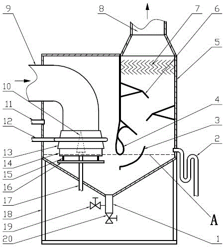
[0023] Such as figure 1 As shown, the high-efficiency wet dust collector includes a support frame 18, a dust collector box 5 located on the support frame 18, an air inlet pipe 9 extending into the side of the dust collector box 5 and fixed, and a dust collector box On the other side of the body 5 is an S-shaped channel composed of upper blades 4, lower blades 3, and water baffles 6, and an exhaust pipe 8 connected to the top of the dust collector box 5, and located at the bottom of the dust collector box 5. The slurry discharge pipe 1, the slurry discharge valve 20 and the flushing valve 19 connected with the slurry discharge pipe 1, and the water supply pipe 11 and the overflow pipe 2 communicated with the dust collector box 5. The exhaust pipe 8 is fixed on the top wall of the dust collector box 5, and the air inlet pipe 9 enters the box from the side wall of the dust collector box 5 and is fixedly connected with the side wall of the dust collector box 5. The outlet of the ...

Embodiment 2

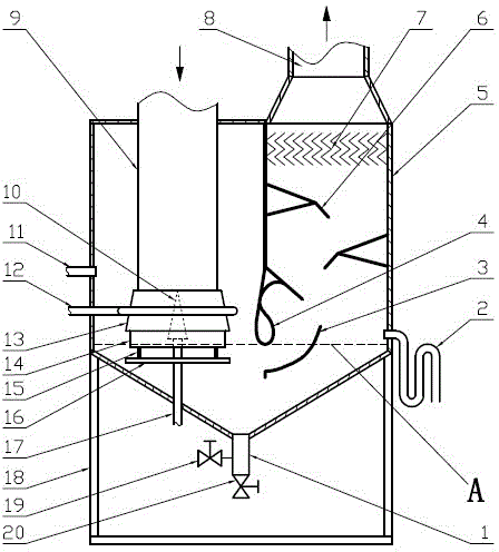
[0027] Such as figure 2 As shown, the inlet pipe 9 of the high-efficiency wet dust collector enters the box body from the top wall of the dust collector box 5 and is fixedly connected with the top wall of the dust collector box 5 . Others are the same as embodiment 1.


PUM


Abstract

The invention relates to an efficient wet dust remover comprising a support frame, a dust remover box body, an air inlet pipe, an upper vane, a lower vane, a water blocking plate, an air exhaust pipe, a pulp discharge pipe, a flushing valve, a water supply pipe and an overflow pipe. The efficient wet dust remover is characterized in that an annular outer water spray head is installed at an outlet of the air inlet pipe; water inlet holes are uniformly formed in the outer wall of the outer water spray head; matrix-shaped water spray holes I are uniformly distributed in the inner wall of the outer water spray head; the outer sides of the water inlet holes are connected with an outer water spray head water inlet pipe; the lower part of the outer water spray head is connected with an annular air inlet pipe spray head; the lower part of the air inlet pipe spray head is connected with a reflection disk; an inner water spray head is arranged in the middle of the outer water spray head; the outer wall of the inner water spray head is provided with matrix-shaped water spray holes II corresponding to the water spray holes I; the bottom of the inner water spray head is connected with an inner water spray head water inlet pipe; and the lower edge of the air inlet pipe spray head is lower than the gage height of the dust remover box body in use state. The efficient wet dust remover is simple in structure and good in purification effect. By utilizing the efficient wet dust remover, the problem of poor dust removal effect on inner dust of a dusty gas group caused by the conventional impact dust remover is solved fundamentally.

Description

technical field [0001] The invention relates to industrial dust removal equipment, in particular to a high-efficiency wet dust collector. Background technique [0002] At present, in the working environment with high temperature and high humidity in industrial and mining enterprises, impulse dust collectors are generally used. The traditional impulse dust collector consists of a support frame, a dust collector box on the support frame, and a dust collector box. The air inlet connected to the body, the S-shaped channel composed of upper blades, lower blades and water baffles set in the box, the exhaust pipe connected with the dust collector box, the slurry discharge pipe set at the bottom of the dust collector box, It is composed of a slurry discharge valve and a flushing valve connected with the slurry discharge pipe, a water supply pipe and an overflow device connected with the dust collector box. When in use, the dusty gas enters the dust collector box from the intake pip...

Claims


Application Information

Patent Timeline
IPC IPC(8): B01D50/00
Inventor 代会民孟冶邹福玉许猛
Owner 代会民
Why Eureka
Try Eureka