
a reaction kettle

A technology of reaction kettle and kettle body, which is applied in the field of reaction kettle, can solve the problems of wasting materials, poor mixing effect of material and liquid, and prolong stirring time, so as to reduce the generation of air bubbles, maintain sufficient contact, and improve the degree of agitation

Active Publication Date: 2016-10-05
NINGBO YUANOU FINE CHEM
View PDF5 Cites 4 Cited by
  • Summary
  • Abstract
  • Description
  • Claims
  • Application Information

AI Technical Summary

Problems solved by technology

However, due to the uneven stirring of the reactor, it will directly affect the quality of the product
If you want to achieve the effect of full mixing, you need to prolong the mixing time, which is time-consuming and labor-intensive, and the work efficiency is low
The agitator is an important part in the reaction kettle. The existing agitator adopts a paddle agitator. When working, the material rotates around the shaft, and the radial fluidity of the material from the periphery to the paddle area is poor, and the mixing effect is relatively poor. In addition, The disturbance of the bottom liquid is small, and the mixing effect of this part of the liquid is even worse
Moreover, the traditional agitator will generate a lot of air bubbles when stirring, which will cause part of the mixture to be wrapped in the air bubbles, causing the mixture to not be fully mixed.
Whether the material can fully react depends on whether the agitator can stir evenly. Although the current agitator can achieve simple stirring effect, it cannot achieve sufficient agitation, so that the material cannot be fully reacted, which wastes the material. Can not get a good reaction solution, in order to solve the above technical problems, a new technical solution is provided

Method used


Image

  • a reaction kettle
  • a reaction kettle

Examples


Embodiment Construction

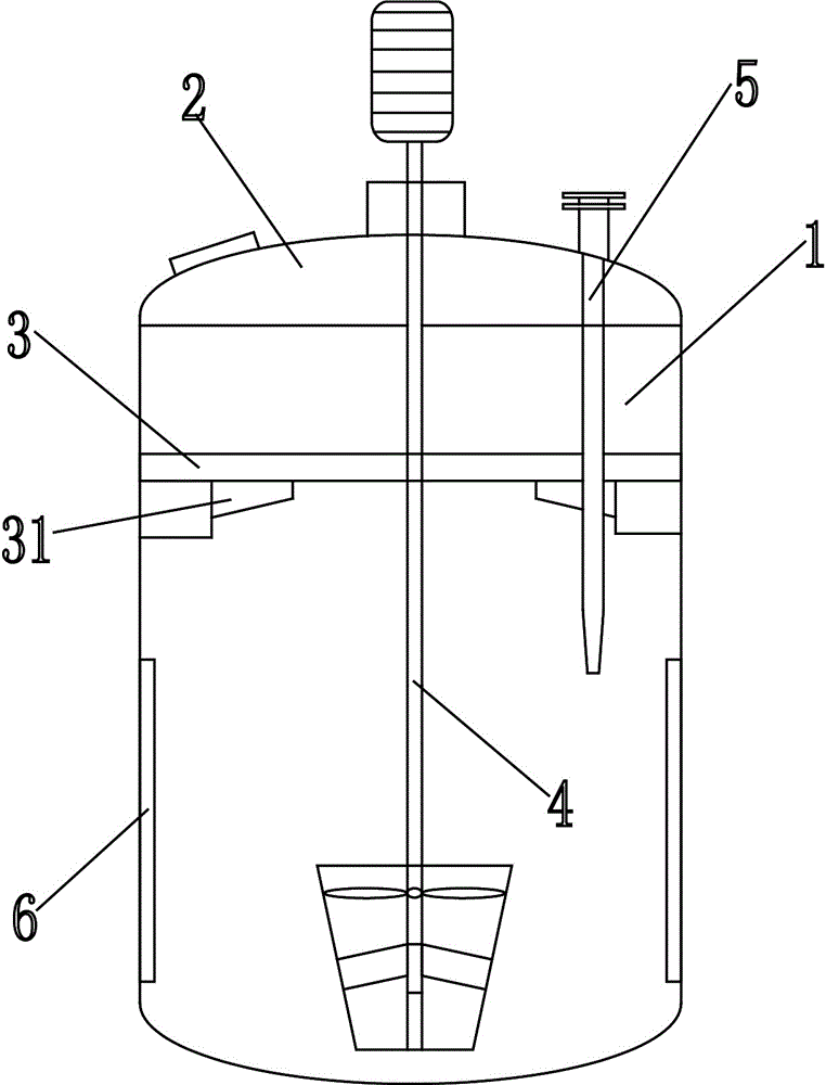
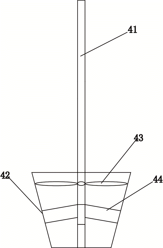
[0011] The present invention will be described in further detail below in conjunction with accompanying drawing and specific embodiment: see figure 1 , figure 2 , a reaction kettle, comprising a kettle body 1, a kettle cover 2 and a stirring device, the upper end of the kettle body 1 is provided with a feed port, the lower end of the kettle body 1 is provided with a discharge port, and the inner wall of the kettle body 1 is provided with There is a boss, the interior of the kettle body is provided with a gland plate 3, and the gland plate 3 is located on the boss, the middle position of the gland plate is provided with a through hole, and the bottom of the gland plate 3 A scraper 31 is provided on the end face and close to the inner wall of the kettle body 1. The stirring device includes an agitator 4, a transmission device, a shaft seal and a bearing seat. The agitator 4 is located inside the kettle body 1, and the shaft The seal and the support seat are located on the kett...


PUM


Abstract

The invention discloses a reaction kettle. The reaction kettle comprises a kettle body, a kettle cover and a mixing device, wherein a lug boss is arranged on the inner wall of the kettle body, a pressure cover plate is arranged in the kettle body and positioned on the lug boss, a through hole is formed in the center of the pressure cover plate, and a scraping knife is arranged at the lower end surface of the pressure cover plate and close to the inner wall of the kettle body; the mixing device comprises a mixer, a transmission device, a shaft seal and a support, the mixer is positioned in the kettle body, the shaft seal and the support are positioned on the kettle cover and connected with the mixer through the transmission device, and plug holes are funnel-shaped and uniformly formed in the kettle cover; a thermometer sleeve tube extends into the kettle, the upper end of the thermometer is fixed on the kettle cover, and a thermometer is arranged in the thermometer sleeve tube; the mixer comprises a mixing shaft, a ring-shaped guide tube, a stator and a rotor; and diversion battens are radially arranged and circumferentially, uniformly distributed on the inner wall of the kettle body, and extend along the axial direction. The reaction kettle disclosed by the invention can reduce the generation of air bubbles during mixing through the novel mixing device, keeps full contact between mixed materials, and improves the mixing effect.

Description

technical field [0001] The invention relates to the field of mechanical accessories, in particular to a reaction kettle. Background technique [0002] Reactor is one of the essential equipment in the production of chemical industry. As we all know, there are many kinds of reactors, which are widely used in petroleum, chemical industry, food, medicine, pesticide, scientific research and other industries. They are used to complete polymerization, condensation, vulcanization, Reaction equipment for chemical processes such as alkylation and hydrogenation. However, due to the uneven stirring of the reactor, it will directly affect the quality of the product. If you want to achieve the effect of full stirring, you need to prolong the stirring time, which is time-consuming and labor-intensive, and the work efficiency is low. The agitator is an important part in the reaction kettle. The existing agitator adopts a paddle agitator. When working, the material rotates around the shaft...

Claims


Application Information

Patent Timeline
Patent Type & Authority Patents(China)
IPC IPC(8): B01J19/18B01J19/20
CPCB01J19/18B01J19/20
Inventor 王淑英
Owner NINGBO YUANOU FINE CHEM
Learn More