Roll shaft and production method thereof

A manufacturing method and roller technology, which are applied in the direction of pretreatment surface, coating, device for coating liquid on the surface, etc., can solve the problems of shortening the service life of the roller, easy adhesion of glue, uneven surface of the prepreg, etc. The effect of good abrasion resistance and anti-adhesion properties, low manufacturing cost, and good electrostatic conductivity

Active Publication Date: 2015-04-01
GUANGDONG SHENGYI SCI TECH
View PDF3 Cites 4 Cited by
  • Summary
  • Abstract
  • Description
  • Claims
  • Application Information

AI Technical Summary

Problems solved by technology

The traditional roller is made of stainless steel, but due to the complicated formula, this traditional roller is easy to stick to glue, resulting in uneven surface of the produced prepreg
[0003] At present, in order to solve the problem of adhesion, a layer of Teflon is usually processed on the surface of the stainless steel roller, but the roller with Teflon on the surface will be w...

Method used


Image

  • Roll shaft and production method thereof
  • Roll shaft and production method thereof
  • Roll shaft and production method thereof

Examples


Embodiment 1

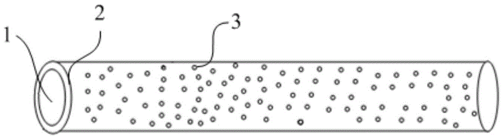
[0047] like figure 1 As shown, the embodiment of the present invention provides a kind of roller shaft, comprises roller shaft body 1, and the surface of roller shaft body 1 is coated with one deck non-stick layer, and non-stick layer 2 is ceramic layer in this embodiment, and ceramic layer The conductive material 3 is embedded, and the conductive material 3 is evenly distributed in the ceramic layer.

[0048] In this embodiment, the roller body 1 is made of stainless steel, the ceramic layer is nano-ceramic coating, and the conductive material 3 is copper powder.

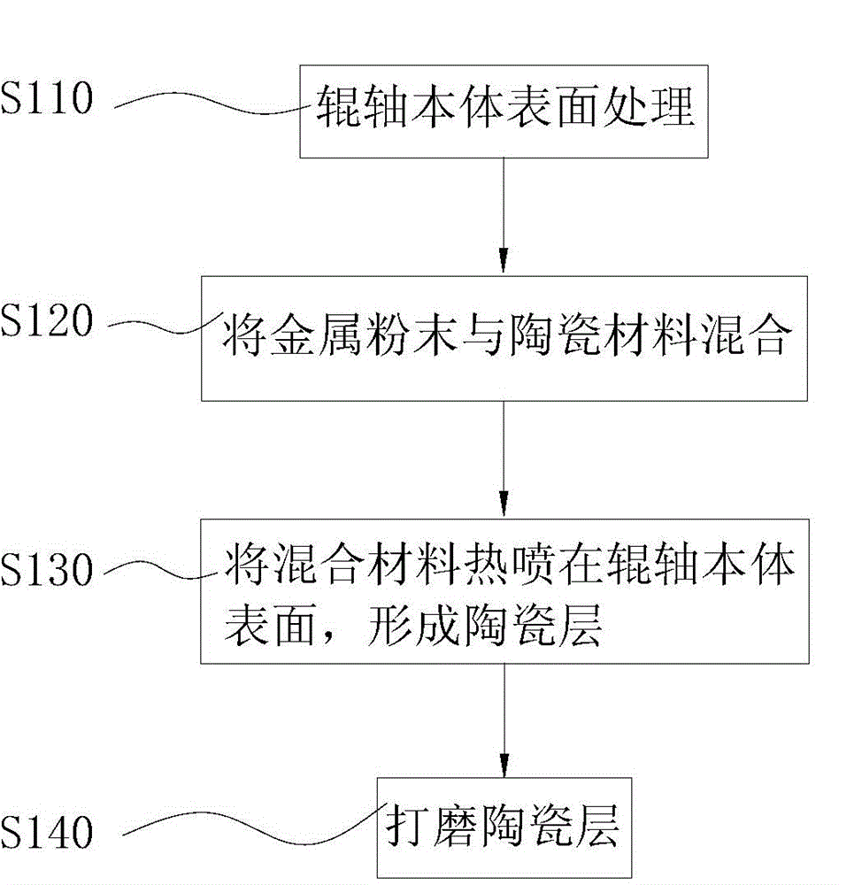
[0049] like figure 2 As shown, the manufacturing steps of this roller shaft are as follows:

[0050] Step S110, surface treatment of the roller body 1: roughen the surface of the roller body 1, and then remove impurities on the surface of the roller body 1, such as dust, oil, etc.;

[0051] Step S120, uniformly mixing the copper powder and the nano-ceramic material;

[0052] Step S130, thermally spraying / sinte...

Embodiment 2

[0055] see figure 1, the embodiment of the present invention provides a kind of roller, comprises roller body 1, and the surface of roller body 1 is coated with one layer of non-stick layer 2, and in this embodiment, non-stick layer 2 is ceramic layer, and ceramic layer is embedded There is conductive material 3, which is evenly distributed in the ceramic layer.

[0056] In this embodiment, the roller body 1 is made of alloy steel, the ceramic layer is a nano-ceramic coating, and the conductive material 3 is a steel block.

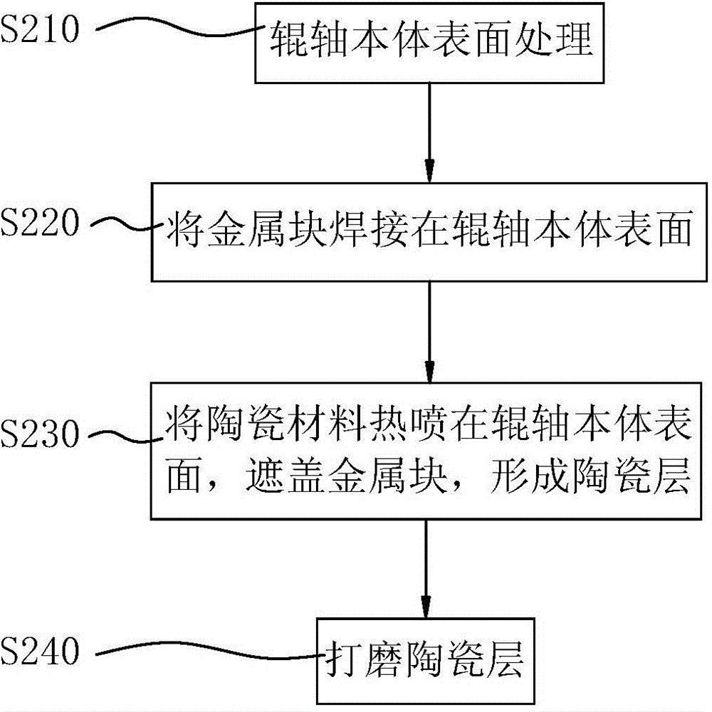
[0057] like image 3 As shown, the manufacturing steps of this roller are as follows:

[0058] Step S210, surface treatment of the roller body 1: roughen the surface of the roller body 1, and then remove impurities on the surface of the roller body 1, such as dust, oil, etc.;

[0059] Step S220, welding a steel block on the surface of the roller body 1;

[0060] Step S230, plasma thermal spraying the nano-ceramic material on the surface of the roller b...

Embodiment 3

[0063] The structure of this embodiment is basically the same as that of Embodiment 1. The only difference is that this embodiment adds a reinforcing part, which can increase the connection strength between the ceramic layer and the roller body. Specifically, the roller body is fixedly provided with The reinforcing part protrudes from the surface of the roller body, and the reinforcing part does not protrude from the surface of the ceramic layer. In this embodiment, the reinforcing part is integrally formed with the roller body.


PUM

PropertyMeasurementUnit
Thicknessaaaaaaaaaa

Abstract

The invention discloses a roll shaft and a production method thereof. The roll shaft comprises a roll shaft body, the surface of the roll shaft body is provided with a nonstick layer, and a conductive material is embedded in the nonstick layer. The nonstick layer arranged on the roll shaft body enhances the wear resistance of the roll shaft, prolongs the service life of the roll shaft and improves the sticking resistance of the roll shaft; and the conductive material embedded in the nonstick layer makes the roll shaft have an excellent electrostatic conduction performance.

Description

technical field [0001] The invention relates to a roller shaft, in particular to a roller shaft with excellent wear resistance and anti-adhesion performance and a manufacturing method thereof. Background technique [0002] Prepreg (B-Stage) is an indispensable semi-finished product used in copper clad laminate (Copper cladlaminate) and multilayer printed circuit board (Multilayer printed circuit board) in the industry. The production method is to soak the glass cloth with glue and then semi-cure in an oven at high temperature. During the production process, the prepreg needs to be transported by rollers. As the glue formula for the production of prepregs becomes more and more complex, the mixing of various resins, especially the addition of inorganic fillers has become one of the commonly used technologies in the copper clad laminate industry. The complexity of the formula and the application of fillers cause varying degrees of damage to the equipment of the prepreg. Espec...

Claims


Application Information

Patent Timeline
IPC IPC(8): B05C11/00B05D1/02B05D1/38B05D3/00
Inventor 马栋杰
Owner GUANGDONG SHENGYI SCI TECH
Why Eureka
Try Eureka