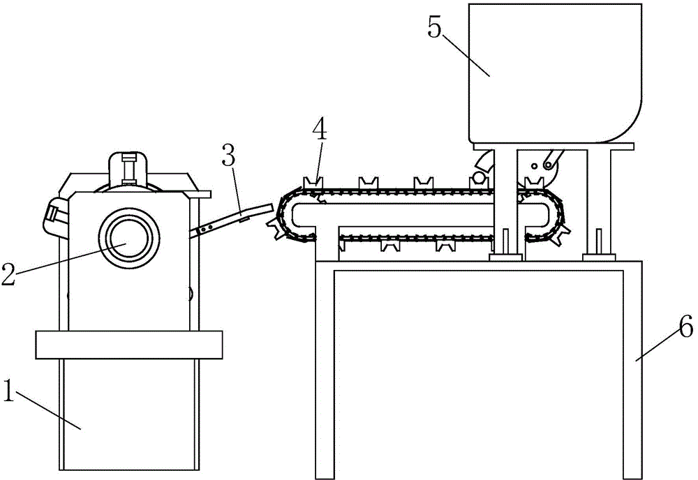
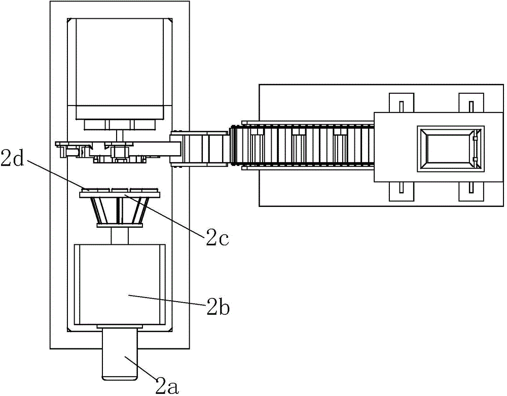
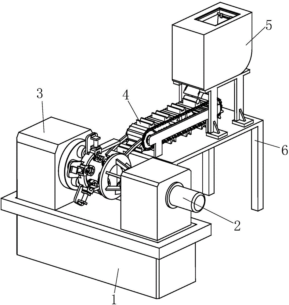
[0032] In order to make the technical means, creative features, goals and effects achieved by the present invention easy to understand, the present invention will be further elaborated below.
[0033] like Figure 1 to Figure 16As shown, a bolt processing integrated machine includes a frame 1, a stamping device 2, a reclaiming mold seat 3, a conveying device 4, a single material conveyor 5 and a workbench 6, and the single material conveyor 5 is fixed on the workbench 6, the conveying device 4 is located at the lower left of the single material conveyor 5, and the conveying device 4 is fixed on the upper left end of the workbench 6, the frame 1 is vertically arranged with the workbench 6, and the take-off The material mold seat 3 is located on the left side of the conveying device 4, and the taking-out mold seat 3 is fixed on the upper rear end of the frame 1, and the stamping device 2 is positioned directly in front of the taking-out mold seat 3, and the stamping device 2 is fixed On the upper front end of rack 1. When carrying out batch processing of bolts, now put the bar into the single-material conveyor 5, start the conveying device 4, and also drive the single-material conveyor 5 to supply materials synchronously, so that the single-material conveyor 5 outputs one bar each time The material just falls on the conveying device 4, and the conveying device 4 is used to convey the bar material to the reclaiming mold base 3, and then the stamping device 2 is started to stamp multiple bars, so that the bolt head is formed at one time, and the diameter reduction is completed. After that, the stamped semi-finished product can be put into the thread rolling machine for thread rolling to complete the thread processing.
[0034] The stamping device 2 includes a stamping cylinder 2a, a box body 2b, an annular pressure plate 2c and a ram 2d, the box body 2b is fixed on the upper front end of the frame 1, and the stamping cylinder 2a is parallel to the frame 1 The width direction is installed on the box body 2b, the annular pressure plate 2c is located at the rear side of the box body 2b, the annular pressure plate 2c is connected with the stamping cylinder 2a, and the pressure head 2d is uniform along the circumferential direction of the annular pressure plate 2c Symmetrically fixed on the rear end surface of the annular pressure plate 2c. When stamping processing is required, start the stamping cylinder 2a to drive the annular pressure plate 2c to move backward, so that the stamping head 2d hits the bar to complete the stamping.
[0035] The reclaiming mold base 3 includes a rear seat 301, an indexing motor 302, a reducing die base 303, a reducing die 304, a display plate 305, an alignment cylinder 306, an outer alignment block 307, a retrieving frame 308, a position limiting hoop 309, reclaiming turntable 310, return spring 311 and inner alignment block 312, the rear seat 301 is fixed on the upper rear end of the frame 1, the indexing motor 302 is fixed on the front end of the rear seat 301, and the shrink The diameter mold base 303 is a disc-shaped structure, the axis of the reduced diameter mold base 303 coincides with the indexing motor 302, and the rear end of the reduced diameter mold base 303 is fixed on the front end surface of the rear seat 301 by screws. A shaft outlet hole 303a is provided at the center of the diameter reduction mold base 303, and the diameter reduction mold 304 is uniformly and symmetrically fixed on the front end face of the diameter reduction mold base 303 with the axis of the shaft outlet hole 303a as the axis of rotation. The quantity of mold 304 is five, and described reducing diameter mold 304 is all provided with reducing diameter mold hole 304a, and described reducing diameter mold base 303 is respectively provided with the guide hole 303b that is communicated with reducing diameter mold hole 304a, so The shaft of the indexing motor 302 passes through the shaft outlet hole 303a and is fixedly connected with the reclaiming turntable 310, and the outer circular surface of the retrieving turntable 310 is evenly and symmetrically provided with five card platforms 310a, and the five card platforms 310a The rear side of each is provided with a semicircular No. 1 shaft bracket 310b, and the return springs 311 are used in pairs to form a reset module, and the reset modules are respectively installed on five card platforms 310a correspondingly. The front ends are respectively correspondingly connected with the inner alignment blocks 312 .
[0036] The inner alignment block 312 includes a semicircular inner alignment body 312a, the middle part of the semicircular inner alignment body 312a is provided with an inner half hexagonal platform 312b, and the rear side of the inner half hexagonal platform 312b is provided with There is a second shaft bracket 312c, the axis of the second shaft bracket 312c coincides with the axis of the semicircular inner alignment body 312a, and the rear end of the semicircular inner alignment body 312a is symmetrically provided with sliding guide posts 312d, the sliding guide posts 312d respectively correspond to sliding fit with the five card platforms 310a, and the return spring 311 is correspondingly sleeved on the sliding guide posts 312d.
[0037] The upper rear end of the limiting hoop 309 is provided with an external beam 309a, and the limiting hoop 309 is connected to the diameter-reducing mold seat 303 through the external beam 309a. 309c and material guide pallet 309d, the ring hoop body 309c is a three-quarter ring structure, the upper end of the ring hoop body 309c is connected with the left end of the outstretched part 309b, and the ring hoop body 309c The right end of the material guide plate 309d is connected to the left end of the material guide plate 309d, and the material guide plate 309d is arranged obliquely to the upper right, and four tooth sockets are evenly distributed along the circumferential direction of the ring hoop body 309c on the ring hoop body 309c 309e, the display discs 305 are correspondingly distributed on the rear side of the four tooth sockets 309e, the display discs 305 are fixedly connected with the ring hoop 309c, and the alignment cylinder 306 is along the radial direction of the reclaiming turntable 310 Correspondingly distributed in front of the display plate 305, the alignment cylinder 306 is correspondingly connected with the display plate 305, and the outer alignment blocks 307 are respectively installed on the alignment cylinder 306, and the outer alignment blocks 307 are respectively corresponding to the The alveolar 309e is slidingly fitted, and the outer alignment block 307 includes an outer alignment body 307a. The front end of the outer alignment body 307a is provided with an outer half hexagonal platform 307b, and the rear side of the outer half hexagonal platform 307b is provided with There is a No. 3 shaft bracket 307c, and the outer half hexagonal platform 307b cooperates with the inner half hexagonal platform 312b to form a hexagonal bolt head groove.
[0038] The left end of the material retrieving frame 308 is fixed on the right part of the material guide pallet 309d, and the material retrieving frame 308 is arranged obliquely to the upper right.
[0039] Utilize the cooperation of the retrieving frame 308 and the conveying device 4 to complete the retrieving, then the bar will roll along the material guide plate 309d until the bar is stuck in the No. 1 shaft bracket 310b, and the indexing motor 302 is started , to drive the reclaiming turntable 310 to rotate, so that the inner side of the bar is stuck in the No. The ring surface plays a good role in limiting the bar to prevent the misalignment of the bar. At the same time, it can be rotated by the reclaiming turntable 310 to ensure that the bar rotates together with the rotation of the reclaiming turntable 310, so that the bar is evenly distributed in the In the No. 1 shaft bracket 310b, four bars are taken at a time. When one of the bars moves to the uppermost end of the take-up turntable 310, the stamping process can be carried out, and the stamping cylinder 2a can be activated to drive the annular pressure plate 2c move, so that the pressure head 2d hits the bar to complete the stamping. During the stamping process, the stamping force will compress the return spring 311 synchronously, so that after the outer alignment block 307 and the inner alignment block 312 cooperate, the outer half-point The hexagonal platform 307b cooperates with the inner half hexagonal platform 312b to form a hexagonal bolt head groove, so that after the bar is subjected to stamping force, it will be formed into a hexagonal bolt head by using the hexagonal bolt head groove, and the rear part of the bar will also be squeezed into the indentation. In the diameter die hole 304a, to complete the diameter reduction processing, that is, the present invention completes the head processing and the diameter reduction processing of the bolt at the same time, and combines the traditional two processes into one process, which greatly improves the efficiency of the bolt processing, and also The coaxiality between the head of the bolt and the threaded part of the bolt to be processed is guaranteed.
[0040] The conveying device 4 comprises a wheel frame 401, a driving wheel 402, a conveying chain plate 403, a feeding pallet 404 and a driven wheel 405, the wheel frame 401 is fixed on the workbench 6, and the driving wheel 402 is installed on the wheel frame The left end of 401, the driven wheel 405 is installed on the right end of the wheel frame 401, the conveying chain plate 403 is wrapped between the driving wheel 402 and the driven wheel 405, and the conveying pallet 404 is evenly installed on the conveying chain plate 403 on the outer surface. When it is necessary to transport bar material, start the driving wheel 402, and drive the conveying chain plate 403 to rotate synchronously, so that the bar material will fall in the conveying pallet 404, and the bar material can be transported to the conveyor belt by using the rotation of the conveying chain plate 403. The leftmost end of the chain plate 403 finally utilizes the pick-up rack 308 to take away the bar stock to complete the transfer of the bar stock.
[0041] The single material conveyor 5 includes a bracket 501, an outer material bin 502, an inner material bin 503, a shifting plate 504, a shifting material cylinder 505, a reclaiming wheel 506, a material guide channel 507, a connecting rod 508 and a runner 509. The bracket 501 is fixed on the upper right end of the workbench 6, the outer material bin 502 is installed on the bracket 501, the upper end of the outer material bin 502 is provided with a feeding port 502a, and the inner material bin 503 is located at the feeding port 502a directly below, the inner material bin 503 is fixedly connected with the outer material bin 502, the upper end of the dial plate 504 is hinged with the upper part of the inner material bin 503, and the material dial cylinder 505 is fixed on the right side of the inner material bin 503 On the wall, the material shifting cylinder 505 is hinged with the lower right part of the shifting plate 504, the lower opening of the inner material bin 503 is set, and the reclaiming wheel 506 is located at the lower opening of the inner material bin 503. The take-up wheel 506 is connected to the inner side wall of the outer material bin 502 through a bearing, and the material guide channel 507 is installed on the lower left side of the opening of the inner material bin 503, and the lower end outlet of the material guide channel 507 is close to the conveying chain plate 403, the runner 509 is fixed on the bottom of the outer bin 502, the runner 509 is crushed on the outer surface of the conveyor chain plate 403, the lower end of the connecting rod 508 is eccentrically hinged with the runner 509, and the connecting rod The upper end of 508 is eccentrically hinged with the pick-up wheel 506 . The reclaiming wheel 506 is provided with a semicircular retrieving groove 506a. The eccentricity of the hinge between the rotating wheel 509 and the connecting rod 508 is smaller than the eccentricity of the hinge between the reclaiming wheel 506 and the connecting rod 508 . What the single material conveyor 5 adopts is the principle of the crank rocker mechanism, and utilizes the characteristic of the reciprocating swing of the rocker to realize the output of bar stock, that is, the crank rocker mechanism is formed by using the reclaiming wheel 506, the connecting rod 508, and the runner 509, wherein, The eccentricity of the hinge of the runner 509 and the connecting rod 508 is the crank radius, and the eccentricity of the hinge of the reclaiming wheel 506 and the connecting rod 508 is the radius of the rocker, so that the crank radius is smaller than the rocker radius, and the crank can complete a circle Rotation, the application is as follows: during the rotation of the conveyor chain plate 403, since the runner 509 is crushed on the outer surface of the conveyor chain plate 403, the runner 509 can be rotated synchronously, and then the connecting rod 508 is driven to drive the take-off The reciprocating rotation of the material wheel 506 makes the feeding chute 506a move back and forth at the lowermost end of the inner feed bin 503 and the feed inlet of the guide channel 507. The groove 506a will be stuck into a bar, and then when the feeding groove 506a swings to the material inlet of the material guide channel 507, the bar is put into the material guide channel 507, and the bar material is transported to the corresponding material guide channel 507. On the feeding pallet 404, the bars in the inner bin 503 can be output by reciprocating in this way; the dial 504 can be driven by the dial cylinder 505, so that the dial 504 is hinged around the upper part of the inner bin 503 Swing at the place to move the bar stock in the inner feed bin 503 towards the position where the feed trough 506a is located, so as to ensure sufficient feeding.
[0042] The height of the right end of the retrieving rack 308 is lower than the height of the horizontal plane where the uppermost end of the conveyor chain plate 403 is located. In this way, when the bar moves to the leftmost end of the conveying chain plate 403, the bar that is about to fall can be caught by the retrieving frame 308, so as to complete the transfer of the bar.
[0043] When working, the operator puts the bar into the inner bin 503 from the feeding port 502a, then starts the drive wheel 402, drives the conveyor chain plate 403 to rotate, and simultaneously makes the runner 509 roll to drive the reclaiming wheel 506 to reciprocate In this way, the retrieving trough 506a will move back and forth at the lowermost end of the inner material bin 503 and the material inlet of the material guide channel 507, and continuously transport the bar in the inner material bin 503 to the material guide channel 507 , that is, single-piece output, the output bar will fall onto the corresponding conveying pallet 404, and then use the rotation of the conveying chain plate 403 to transport the bar to the leftmost end of the conveying chain plate 403, and then use the take-out The material rack 308 catches the bar that is about to fall to complete the transfer of the bar. After that, the index motor 302 is started to drive the reclaiming turntable 310 to rotate, so that the bar on the reclaimer 308 is snapped into the No. 1 shaft bracket In 310b, the indexing motor 302 continues to rotate until the first bar moves to the uppermost position of the reclaiming turntable 310, the indexing motor 302 brakes, starts the stamping cylinder 2a, and drives the pressing head 2d to press on the bar correspondingly On the surface, the head of the bolt can be formed, and at the same time, the diameter reduction of the bolt can be realized to improve the efficiency of the bolt processing. After forming, the stamping cylinder 2a is reset, and the operator takes out the semi-finished product, and then loads it into the thread rolling machine to process the thread. Such cyclic operation can realize batch processing of bolts.
[0044]The basic principles, main features and advantages of the present invention have been shown and described above. Those skilled in the art should understand that the present invention is not limited by the above-mentioned embodiments, and what are described in the above-mentioned embodiments and description are only the principles of the present invention. Without departing from the spirit and scope of the present invention, the present invention also has various Variations and improvements all fall within the claimed invention. The protection scope of the present invention is defined by the appended claims and their equivalents.