
Workpiece clamping device provided with rails with longitudinal moving functions for machine tool

A technology of longitudinal movement and workpiece clamping, which is applied in the direction of honing machine tools, grinding workpiece supports, manufacturing tools, etc. It can solve the problems of reducing the efficiency of adjustment, getting stuck on the slideway, and reducing the effect, so as to reduce the probability and achieve good parallelism. , to ensure the effect of service life

Active Publication Date: 2015-04-01
金丽丹
View PDF7 Cites 3 Cited by
  • Summary
  • Abstract
  • Description
  • Claims
  • Application Information

AI Technical Summary

Problems solved by technology

[0002] When the existing honing or general grinding machine is processed, it needs to clamp the workpiece. For the general processing machine, the workpiece needs to be clamped and fixed by moving two clamping blocks. However, when adjusting the clamping block At the same time, if the clamping block is relatively long, it is necessary to use at least two bolts to rotate on the support block, so that the top of the bolt is pressed against the clamping block, and the clamping block moves, the adjustment of the two bolts, and If the adjustment is made separately, it is easy to make the clamping block move obliquely during the movement, and get stuck on the slideway, causing damage to the slideway, and the two bolts are adjusted separately, which reduces the adjustment efficiency and the effect is greatly reduced

Method used

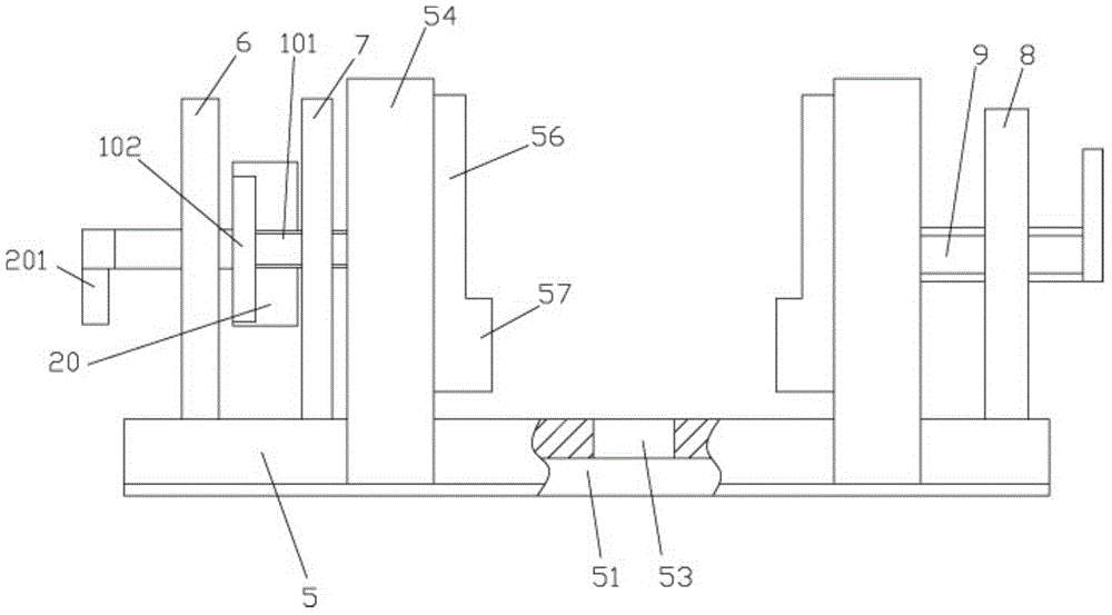
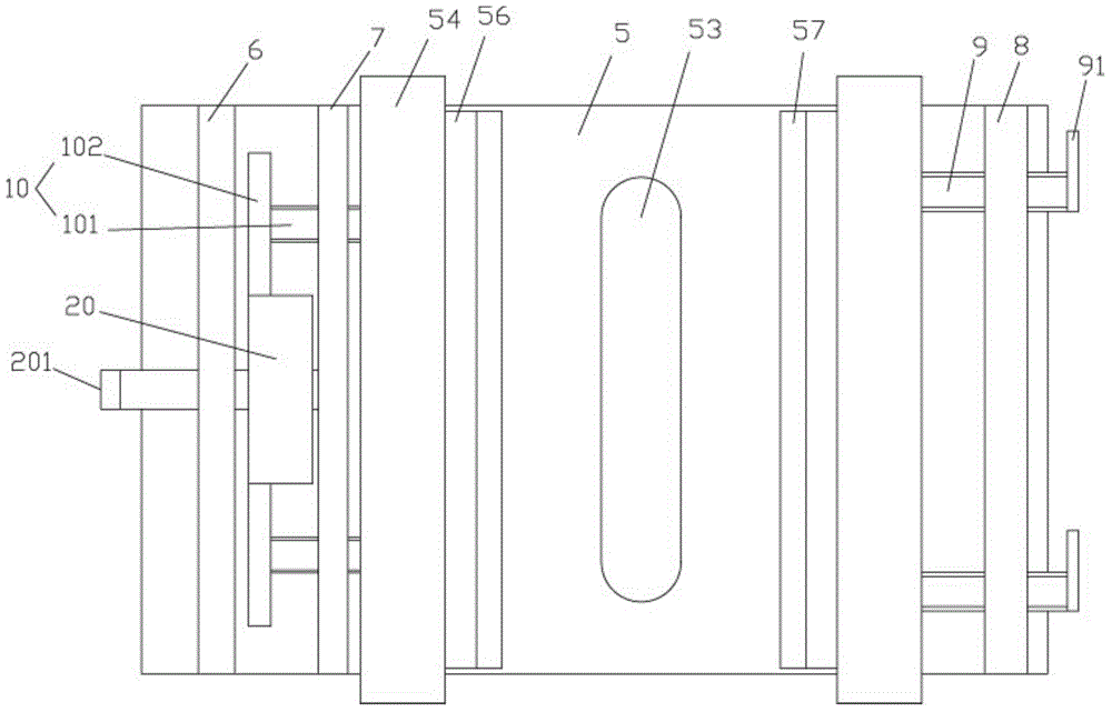
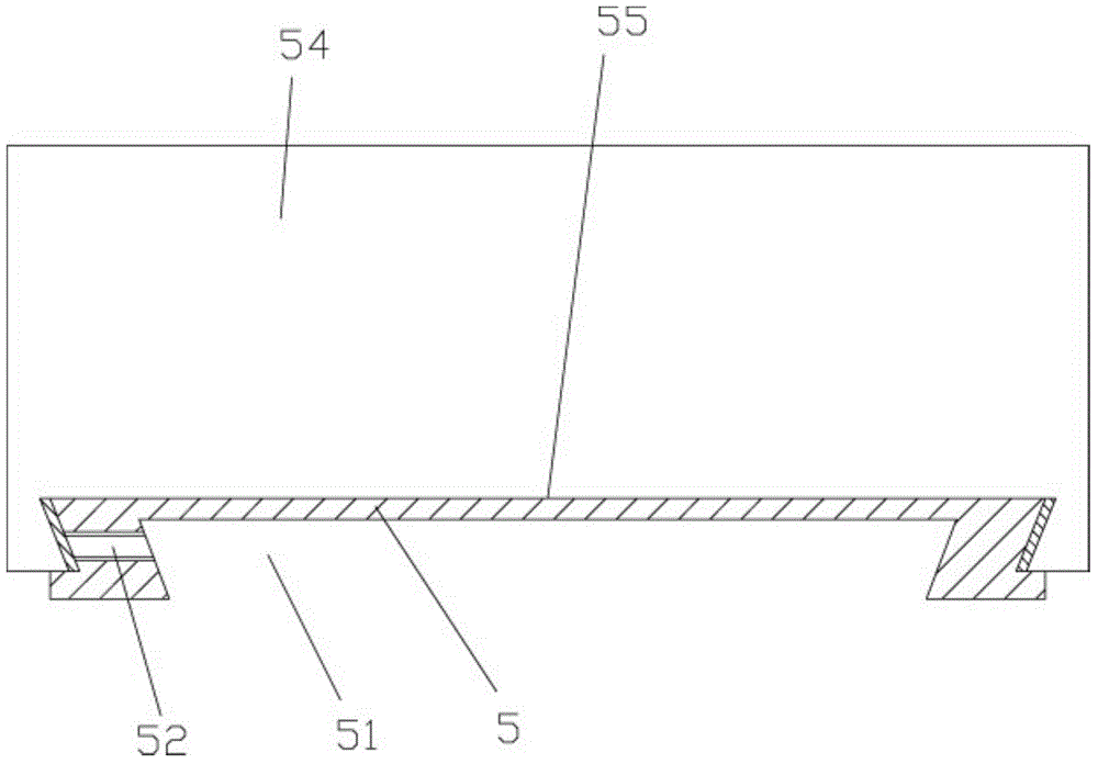

Image

  • Workpiece clamping device provided with rails with longitudinal moving functions for machine tool
  • Workpiece clamping device provided with rails with longitudinal moving functions for machine tool
  • Workpiece clamping device provided with rails with longitudinal moving functions for machine tool

Examples


Embodiment Construction

[0017] The present invention will be described in detail below in conjunction with accompanying drawings and specific preferred embodiments, so that the advantages and features of the present invention can be more easily understood by those skilled in the art. range is limited.

[0018] Examples, see e.g. Figures 1 to 3 As shown, a machine tool track has a workpiece clamping device for longitudinal movement, including a longitudinal adjustment chassis 5, the bottom of the longitudinal adjustment chassis 5 has a bottom chute 51, and one side wall row of the bottom chute 51 has longitudinal fixing screw holes 52. The middle part of the longitudinal adjustment chassis 5 has a waist-shaped through groove 53, and the longitudinal adjustment chassis 5 is provided with two adjustment clamping blocks 54. The bottom of the block 54 has a main groove 55, and the upper part of the longitudinal adjustment chassis 5 is inserted into the main groove 55;

[0019] The upper left side of th...


PUM


Abstract

The invention discloses a workpiece clamping device provided with rails with longitudinal moving functions for a machine tool. The workpiece clamping device comprises a longitudinal adjusting base plate. A bottom slide groove is formed in the bottom of the longitudinal adjusting base plate, longitudinal fixing screw holes are formed in a side wall of the bottom slide groove, a kidney-shaped straight slot is formed in the middle of the longitudinal adjusting base plate, two adjusting clamping blocks are arranged on the longitudinal adjusting base plate and are arranged on two sides of the kidney-shaped straight slot, main grooves are formed in the bottoms of the adjusting clamping blocks, and the upper portion of the longitudinal adjusting base plate is inserted in the main grooves. The workpiece clamping device has the advantages that a middle adjusting gear can rotate, so that two adjusting gear screws can synchronously move, the adjusting clamping block on the left side of the kidney-shaped straight slot can assuredly parallelly move, high adjusting efficiency can be guaranteed, the workpiece clamping device is good in parallelism, the probability that the adjusting clamping blocks are jammed on the longitudinal adjusting base plate can be reduced, and the service life of equipment can be guaranteed.

Description

Technical field: [0001] The invention relates to the technical field of machining, and more specifically relates to a workpiece clamping device with longitudinal movement of a machine tool rail. Background technique: [0002] When the existing honing or general grinding machine is processed, it needs to clamp the workpiece. For the general processing machine, the workpiece needs to be clamped and fixed by moving two clamping blocks. However, when adjusting the clamping block At the same time, if the clamping block is relatively long, it is necessary to use at least two bolts to rotate on the support block, so that the top of the bolt is pressed against the clamping block, and the clamping block moves, the adjustment of the two bolts, and If they are adjusted separately, it is easy to cause the clamping block to move obliquely during the movement, and get stuck on the slideway, causing the slideway to be damaged, and the two bolts are adjusted separately, which reduces the ad...

Claims


Application Information

Patent Timeline
IPC IPC(8): B24B41/06B24B33/10
CPCB24B33/10B24B41/06
Inventor 杨建华
Owner 金丽丹
Learn More