A magnetic rotary pick-and-place device

A pick-and-place device and magnetic suction technology, applied in the direction of program-controlled manipulators, manufacturing tools, chucks, etc., can solve problems such as short life, complex structure, and small air suction adsorption force, and achieve long service life, firm adsorption, and easy implementation Effect

Active Publication Date: 2016-03-30
GOERTEK INC
View PDF9 Cites 3 Cited by
  • Summary
  • Abstract
  • Description
  • Claims
  • Application Information

AI Technical Summary

Problems solved by technology

[0004] The purpose of the present invention is to provide a magnetic suction rotary pick-and-place device, aiming at solving the complex structure and high cost of the device in the prior art that sucks up the product and puts it down after rotating a certain angle, and the air suction also has small adsorption force, Easy to leak and short life

Method used


Image

  • A magnetic rotary pick-and-place device
  • A magnetic rotary pick-and-place device
  • A magnetic rotary pick-and-place device

Examples


Embodiment Construction

[0033] In order to make the objectives, technical solutions and advantages of the present invention clearer, the following further describes the present invention in detail with reference to the accompanying drawings and embodiments. It should be understood that the specific embodiments described herein are only used to explain the present invention, but not to limit the present invention.

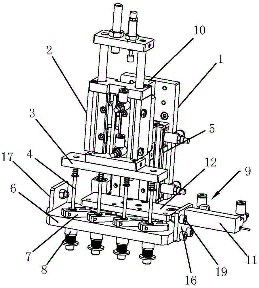
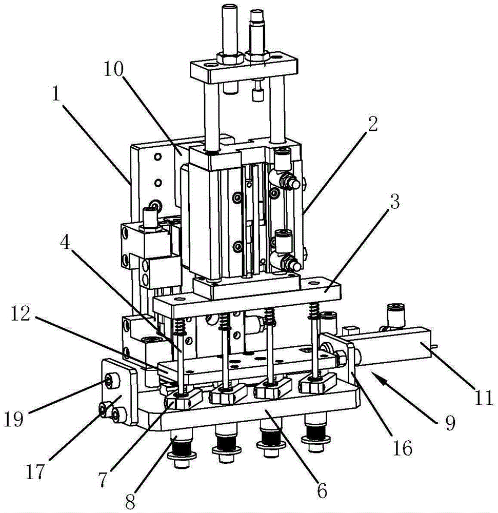
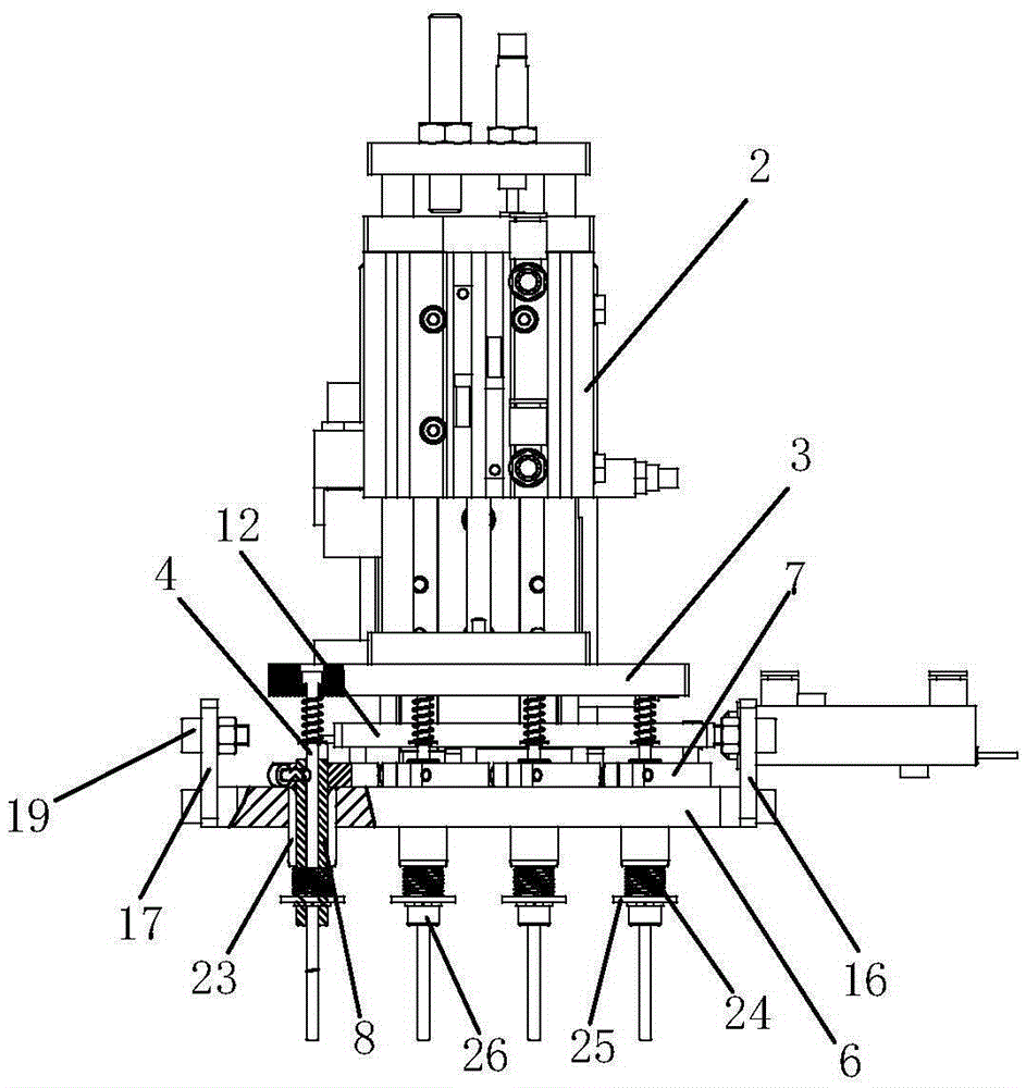
[0034] figure 1 , figure 2 with image 3 The schematic diagrams of the structure of the magnetic rotary pick-and-place device provided by the present invention are respectively shown. For ease of description, only the parts related to the present invention are shown in the figure.

[0035] The magnetic rotary pick-and-place device includes a vertical fixed plate 1, and a product fixing mechanism and a product rotary pick-and-place mechanism are staggered on the same side of the fixed plate 1, wherein:

[0036] The product fixing mechanism includes a first cylinder 2 that is connected to the fixe...


PUM


Abstract

The invention relates to the technical field of electronic product assembly and provides a magnet attraction rotation picking and placing device. The device comprises a fixing plate. A product fixing mechanism and a product rotation picking and placing mechanism are arranged on the fixing plate. The product fixing mechanism comprises a first air cylinder, a first connection plate and a plurality of non-magnetic ejection rods. The product rotation picking and placing mechanism comprises a picking and placing unit and a rotation unit. The picking and placing unit comprises a second air cylinder, a second connection plate and a plurality of first through holes corresponding to the non-magnetic ejection rods. Corresponding torsion blocks are arranged on the sides of the upper ends of the first through holes close to the first connection plate. Hollow magnet absorption rods for penetrating the non-magnetic ejection rods are arranged in the first through holes, the upper ends of the magnet absorption rods are fixedly connected with the torsion blocks, the lower ends extend to the sides away from the torsion blocks, and the torsion blocks are connected with rotation units controlling the circumference rotation of the torsion blocks, accordingly, a plurality of magnetic products are attracted simultaneously and are put down when rotating to preset angles. According to the device, the structure is simple, power connection is not needed, an air source is used as power, the absorption is firm, and the service life is long.

Description

Technical field [0001] The invention belongs to the technical field of electronic product assembly, and in particular relates to a magnetic suction rotating pick-and-place device. Background technique [0002] The assembly of electronic components is mostly completed by automatic assembly lines, and the working mode of sucking up and rotating the products to a certain angle and then putting them down is widely used in automatic assembly line production. [0003] At present, for the working mode where the product is sucked up and rotated at a certain angle and then put down, the vacuum sucker is usually used to absorb the product, and the motor is used to drive the product to rotate. The overall structure is complicated, the cost is high, and the suction force is also small and easy. Air leakage and short life. Summary of the invention [0004] The purpose of the present invention is to provide a magnetic suction rotary pick-and-place device, which aims to solve the problem of the c...

Claims


Application Information

Patent Timeline
Patent Type & Authority Patents(China)
IPC IPC(8): B25J9/14B25J15/06
Inventor 杜鹏飞
Owner GOERTEK INC
Why Eureka
Try Eureka