
A Connected Hydraulic Energy Feed Suspension System

A suspension system and energy feeding technology, which is applied in the field of vehicle engineering, can solve problems such as energy recovery, and achieve the effects of convenient layout, small speed fluctuation, and consistent rotation direction

Inactive Publication Date: 2016-09-07
HUNAN UNIV
View PDF5 Cites 0 Cited by
  • Summary
  • Abstract
  • Description
  • Claims
  • Application Information

AI Technical Summary

Problems solved by technology

[0006] Aiming at the energy loss in the process of traditional passive and semi-active suspension attenuating suspension vibration, the present invention aims to provide a connected hydraulic energy-feeding suspension system, which can effectively solve the problem of vehicle suspension vibration energy recovery The problem

Method used


Image

  • A Connected Hydraulic Energy Feed Suspension System
  • A Connected Hydraulic Energy Feed Suspension System
  • A Connected Hydraulic Energy Feed Suspension System

Examples


Embodiment Construction

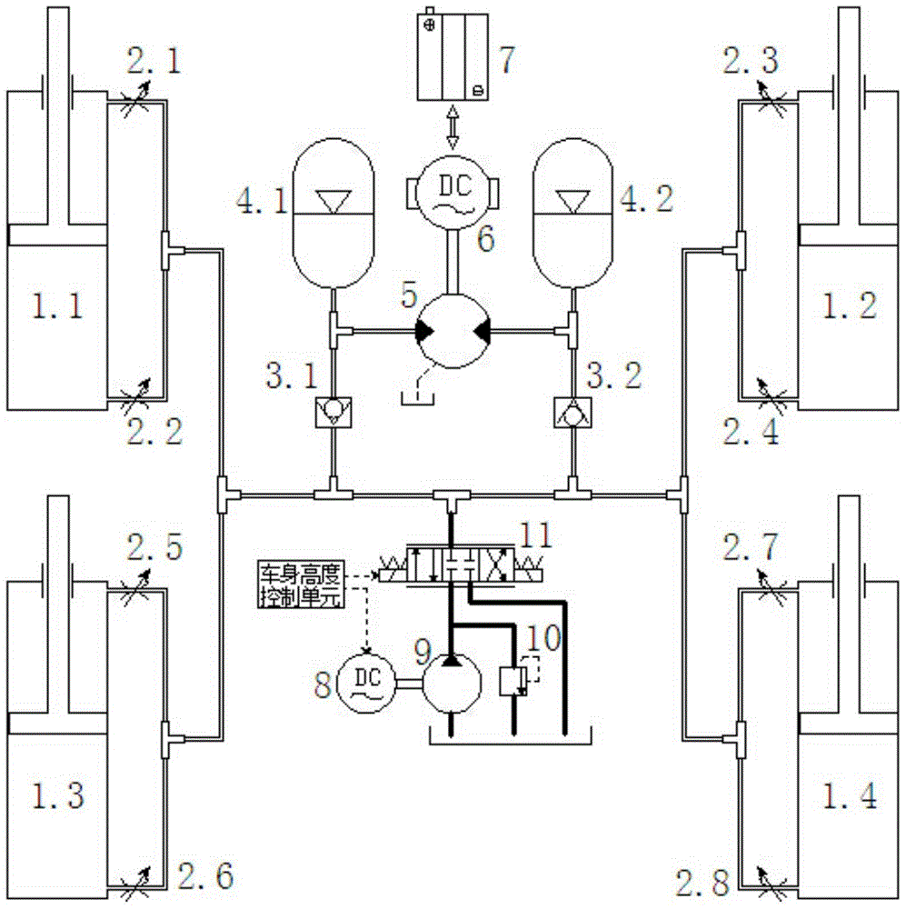
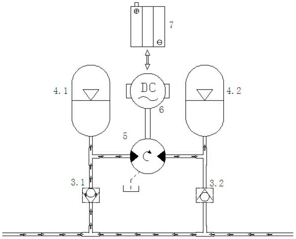
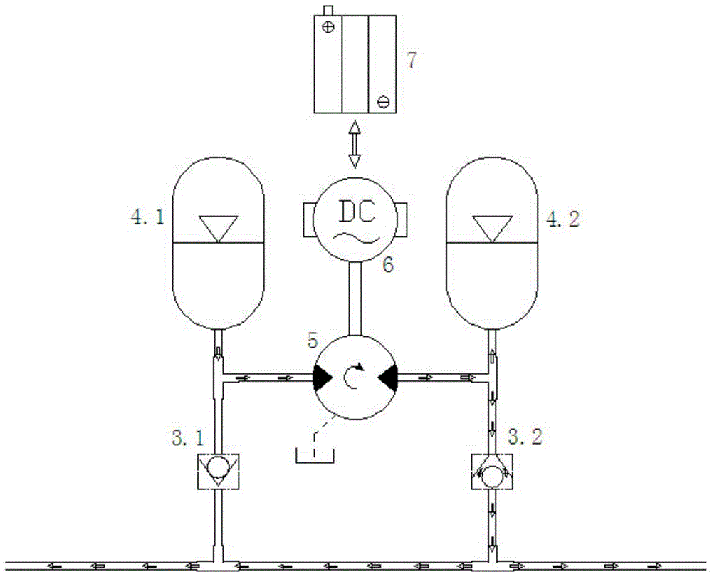
[0028] A fully connected hydraulic energy storage suspension system, such as figure 1 As shown, the oil ports of the rodless cavity and the rod cavity of hydraulic cylinders 1.1, 1.2, 1.3, and 1.4 are all connected through damping valves, oil pipes and three-way joints to form a fully connected hydraulic circuit. The first one-way valve 3.1, the second one-way valve The combination of the valve 3.2 and the first accumulator 4.1 and the second accumulator 4.2 forms a hydraulic rectification circuit, and the hydraulic motor 5 drives the DC generator 6 as an energy recovery unit installed on the first accumulator 4.1 and the second accumulator 4.2 Among them, the oil pump 9, the overflow valve 10 and the proportional solenoid valve 11 form the vehicle height adjustment unit.

[0029] The outlets of the two working chambers of the hydraulic cylinder are respectively connected to an adjustable damping valve, and the adjustable damping valve affects the speed of oil in and out of th...


PUM


Abstract

The invention discloses a communicated hydraulic energy feeding suspension system. The communicated hydraulic energy feeding suspension system is used for recovering vehicle suspension vibration energy. The communicated hydraulic energy feeding suspension system comprises a plurality of hydraulic cylinders, wherein a rod cavity and a rodless cavity of each hydraulic cylinder are communicated with a main oil pipe through pipelines, the main oil pipe is communicated with a first energy accumulator through a first one-way valve and is communicated with a second energy accumulator through a second one-way valve, and the first energy accumulator and the second energy accumulator are connected through a hydraulic motor, so as to form a hydraulic rectification circuit; the hydraulic motor is connected with a generator. According to the communicated hydraulic energy feeding suspension system, on the basis that oil gas suspension functions are realized by adopting the cooperation between the energy accumulators, the direct-current generator is driven by the hydraulic motor, so as to realize the recovery of energy from a suspension system; the communicated hydraulic energy feeding suspension system has the advantages of low technical cost, convenience in layout, high efficiency, reliability, economical efficiency and practicability.

Description

technical field [0001] The invention relates to the field of vehicle engineering, in particular to the key part of the vehicle chassis - the suspension system, which is especially suitable for medium and heavy vehicles and multi-axle vehicles, and has the advantages of convenient layout, low technical cost, high efficiency, reliability, economy and practicality. Background technique [0002] The function of the vehicle suspension is to transmit the force and moment acting between the wheel and the frame, and buffer the impact force transmitted from the uneven road to the frame or body, and attenuate the vibration caused by it, so as to ensure that the car can run smoothly , to ensure the comfort of the ride and the integrity of the cargo. [0003] Both traditional passive suspension and semi-active suspension use shock absorbers to absorb vehicle vibration, and the throttling effect of damping converts the vibration energy of the vehicle into heat energy and consumes it. In...

Claims


Application Information

Patent Timeline
Patent Type & Authority Patents(China)
IPC IPC(8): B60G13/18
Inventor 周创辉文桂林
Owner HUNAN UNIV
Learn More