Elevator damping device with adaptability

A damping device and adaptable technology, applied in transportation and packaging, shock absorbers, mechanical equipment, etc., can solve the problems of passenger danger, inability to use elastic coefficient springs, complex structure, etc., to improve comfort and reliability, The effect of smooth damping force and improved safety performance

Inactive Publication Date: 2015-04-01
CHONGQING HEHANG TECH
View PDF11 Cites 4 Cited by
  • Summary
  • Abstract
  • Description
  • Claims
  • Application Information

AI Technical Summary

Problems solved by technology

[0003] The uplink and downlink of van elevators are generally achieved by mechanical traction, and the structure is relatively complex. Due to problems such as the use environment, cycle, equipment aging, and quality, it will cause the elevator car body to fall without constraints or limited constraints, which is relatively complex. serious safety issue
In the prior art, in order to solve the serious danger to the passengers caused by the rigid bottoming of the elevator car body (directly falling to the bottom of the hoistway), a buffer device is installed at the bottom of the hoistway; the buffer device is a hydraulic buffer for high-speed elevators, and generally The structure of the buffer spring is adopted, and this consideration is mainly the relationship between the elastic coefficient of the spring, the stroke and the elevator car body. Therefore, high-speed elevators cannot use springs with a large elastic coefficient, otherwise there will be obvious rigid bottoming feeling. resulting in accidents; the main thing is that the above-mentioned buffer structure is not adaptable according to the whereabouts of the elevator car body, so it cannot be buffered according to the falling situation

Method used


Image

  • Elevator damping device with adaptability

Examples


Embodiment Construction

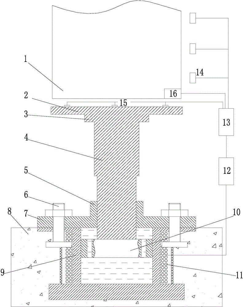
[0025] figure 1 It is a structural schematic diagram of the present invention, as shown in the figure: the elevator of this embodiment has an adaptive damping device, including a magnetorheological damping body and a control system;

[0026] The control system includes:

[0027] The electromagnetic coil 11 is used to provide an electromagnetic field for the magnetorheological damping body;

[0028] A power supply unit 12, configured to provide power for the electromagnetic coil;

[0029] The falling parameter detection unit is used to detect the falling parameter of the elevator car body 1;

[0030] The central processing unit 13 is configured to receive the data signal of the drop parameter detection unit and issue a power supply command to the power supply unit according to the signal.

[0031] The elevator casing 1 will have different speeds and inertias according to different heights and loads during the fall process, so for the buffer device, it is necessary to provide...


PUM


Abstract

The invention discloses an elevator damping device with adaptability. The elevator damping device comprises a magnetorheological damping body and a control system. Parameters of magnetorheological fluid are regulated according to parameters in an abnormal falling process, if the falling speed is higher, the electrification current is increased, and the magnetorheological fluid is thickened for increasing the damping force, in addition, the damping force is gradually increased in the bottom touching process of an elevator life car body, meanwhile, the electrification current can be reduced after the speed of the elevator life car body is decelerated in the damping process, a gradually decreased damping force is formed, the damping is fast and gentle combined with the general hydraulic damping and the damping of an ordinary spring, and the damping force is adjustable, so the elevator damping device can be applicable to high-speed and low-speed elevators, the descending buffer smoothness and the sufficient variable damping force are realized, and in addition, the any-time dynamic application effects are achieved, so that the comfort and the reliability before the elevator life car body touches the bottom and at the moment of making contact with a buffer assembly can be effectively improved, and the safety performance of the elevators is improved.

Description

technical field [0001] The invention relates to a safety system for special equipment, in particular to a safety system for a van elevator when it hits the bottom. Background technique [0002] The van elevator is a means of transportation for vertical transportation, which is closely related to people's daily life; the existing van elevator is mainly composed of a traction machine, a control cabinet, an elevator car body, guide rails, etc. Downlink; In order to realize uplink and downlink and install related equipment, elevator shafts will be built in buildings or other places where van elevators are used to achieve smooth operation. [0003] The uplink and downlink of van elevators are generally achieved by mechanical traction, and the structure is relatively complex. Due to problems such as the use environment, cycle, equipment aging, and quality, it will cause the elevator car body to fall without constraints or limited constraints, which is relatively complex. serious ...

Claims


Application Information

Patent Timeline
Patent Type & Authority Applications(China)
IPC IPC(8): B66B5/28F16F9/53
CPCB66B5/282F16F9/535
Inventor 徐培龙叶敏徐建刘启帆
Owner CHONGQING HEHANG TECH
Why Eureka
Try Eureka