
Vehicle body hydraulic turnover machine

A hydraulic flipping and vehicle body technology, applied in fluid pressure actuating devices, hoisting devices, hoisting devices, etc., can solve the problems of difficult flipping, low efficiency, poor versatility, etc., and achieve the effect of reducing errors

Inactive Publication Date: 2015-04-01
CRRC QISHUYAN CO LTD
View PDF7 Cites 4 Cited by
  • Summary
  • Abstract
  • Description
  • Claims
  • Application Information

AI Technical Summary

Problems solved by technology

[0002] The existing turning machine is a split structure without connecting the main beam in the middle, and the turning action is performed by mechanical transmission, resulting in insufficient turning rigidity, and problems such as difficult turning, poor safety, low efficiency, and poor versatility during operation

Method used


Image

  • Vehicle body hydraulic turnover machine
  • Vehicle body hydraulic turnover machine
  • Vehicle body hydraulic turnover machine

Examples


Embodiment Construction

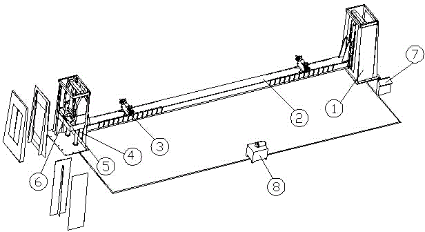
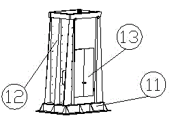
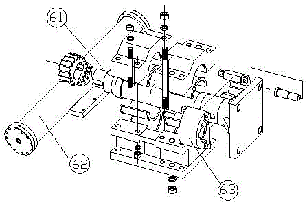
[0015] Such as figure 1 , 2 , 3 and 4 show a hydraulic turning machine for car body, including frame 1, main beam 2, turning clamping device 3, electrical control cabinet 7 and hydraulic station 8. The main beam 2 is connected to the frame 1 at the left and right ends, Two ends of the main beam 2 are close to the frame 1 with flipping clamping devices 3, one side of the main beam 2 is provided with a hydraulic station 8, and one side of the frame 1 is provided with an electrical control cabinet 7, the main beam 2 is a welding box Beam structure, the frame 1 is a door box structure. The frame 1 includes a base 11, a box body 12 and an assembly door 13. The assembly door 13 is located in the middle of the box body 12, and two lifting cylinders 4 are fixed on the base 11. Anchor bolts are uniformly distributed on the base 11, and a supporting lifting platform 5 is provided inside the box body 12. The supporting lifting platform 5 moves up and down along the guide rails on both side...


PUM


Abstract

The invention relates to the technical field of vehicle body production or repair equipment, in particular to a vehicle body hydraulic turnover machine. The vehicle body hydraulic turnover machine comprises a rack, a main beam, a turnover clamping device, an electric control cabinet and a hydraulic station, wherein the main beam is of a welded box beam structure; the rack is of a door type box structure; a supporting lifting platform is arranged in the box body and moves up and down along guide rails on the two sides of the box body through a lifting oil cylinder; the supporting lifting platform is provided with a hydraulic swing rotating mechanism; the lifting oil cylinder and a swing oil cylinder are both provided with a synchronous valve and double locks; the turnover clamping device is a lead screw clamping device with self-locking capacity; clamping interlock control devices are arranged on the two sides of the lead screw clamping devices. When hydraulic pressure is adopted for transmission by the improved vehicle body hydraulic turnover machine, synchronous coordination is performed by using a hydraulic control system to reduce the error probably produced during operation between two groups of transmission mechanisms, so the relatively balanced, stable, safe and reliable operation of equipment lifting and turnover action is realized.

Description

Technical field [0001] The invention relates to the technical field of car body production or repair equipment, in particular to a car body hydraulic turning machine. Background technique [0002] The existing turning machine has a split structure with no main beams connected in the middle, and mechanical transmission is used for turning execution actions, resulting in insufficient turning rigidity, and problems such as turning difficulty, poor safety, low efficiency, and poor versatility in operation. Summary of the invention [0003] In order to overcome the above-mentioned existing shortcomings, the present invention provides a vehicle body hydraulic turning machine. [0004] The technical solution adopted by the present invention to solve its technical problems is: a hydraulic turning machine for car body, including a frame, a main beam, a turning clamping device, an electrical control cabinet and a hydraulic station. The main beam is connected to the frame at the left and right...

Claims


Application Information

Patent Timeline
Patent Type & Authority Applications(China)
IPC IPC(8): B66F19/00F15B15/20
CPCB66F19/00F15B15/26
Inventor 唐维军袁志伟张春红
Owner CRRC QISHUYAN CO LTD
Learn More