
Needle driving mechanism for variable space embroidery machine

A driving mechanism and embroidery machine technology, which is applied to the mechanism of embroidery machines, embroidery machines, mechanical equipment, etc., can solve the problems of strict restrictions on the scope of use, difficulty in replacement, and difficulty in installing power shafts.

Inactive Publication Date: 2015-04-01
ZHEJIANG SCI-TECH UNIV
View PDF7 Cites 1 Cited by
  • Summary
  • Abstract
  • Description
  • Claims
  • Application Information

AI Technical Summary

Problems solved by technology

[0002] The needle driving mechanism is one of the core components of the embroidery machine, which has high requirements on the motion characteristics. At present, the needle driving mechanism of the embroidery machine mainly adopts the horizontal arrangement of the power shaft. When the distance is small, the power shaft is difficult to install.
The cam transmission mechanism widely used in the market, the cam wears seriously, it is difficult to replace and the design of the cam is difficult, so it is not suitable for embroidery occasions with heavy loads
The cam needle drive mechanism is directly connected to the needle drive slider by a single cam. The movement speed and stroke of the slider cannot be adjusted, and the scope of use is strictly limited.

Method used


Image

  • Needle driving mechanism for variable space embroidery machine
  • Needle driving mechanism for variable space embroidery machine
  • Needle driving mechanism for variable space embroidery machine

Examples


Embodiment Construction

[0020] The present invention will be further described below in conjunction with accompanying drawing.

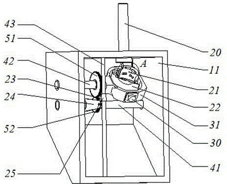
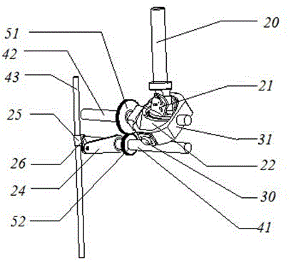
[0021] Such as Figure 1-8 As shown, the needle driving mechanism of the displacement space embroidery machine of the present invention mainly includes a box body 11, a driving mechanism, and a power output part. The shape of the box body 11 is a right-angled trapezoid, and the driving mechanism mainly includes two parts: a displacement space mechanism and a gear mechanism. The power output part is mainly realized through the rotation of the pinion shaft 41, which drives the swing arm 24 to swing up and down to push the needle drive slider 25 to slide up and down.

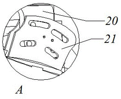
[0022] The displacement space mechanism is composed of a main shaft 20, an elbow 21, a bearing 27, an annular swing shaft 22, and a swing ring 31. The end of the main shaft 20 is flat and has a fixing hole on it, which can cooperate with the adjustment ring on the elbow 21 for adjustment and installation. angl...


PUM


Abstract

The invention discloses a needle driving mechanism for a variable space embroidery machine. The needle driving mechanism mainly comprises a box body, a driving mechanism and a power output part, wherein the outline of the box body is of a right-angle trapezoid, the driving mechanism mainly comprises a variable space mechanism and a gear mechanism; an oscillating arm is driven to swing up and down by power output which is mainly generated by the rotation of a rotating pinion shaft to propel a needle to drive a slide block to slide up and down, in order to output the power. According to the needle driving mechanism for variable space embroidery machine disclosed by the invention, a main shaft inputs power, the variable space mechanism drives an oscillating ring to swing to drive an oscillating shaft to swing, and the power is output by gear engagement to achieve the up and down slide of a needle driving block. A needle rod stroke and a movement speed can be adjusted by adjusting the radius part of a meshing gear according to actual conditions.

Description

technical field [0001] The invention relates to a needle driving mechanism of an embroidery machine, in particular to a needle driving mechanism of a displacement space embroidery machine. Background technique [0002] The needle driving mechanism is one of the core components of the embroidery machine, which has high requirements on the motion characteristics. At present, the needle driving mechanism of the existing embroidery machine mainly adopts the horizontal arrangement of the power shaft. When the distance is small, the power shaft is difficult to install. The cam transmission mechanism widely used in the market has severe cam wear, difficult replacement and difficult cam design, and is not suitable for large-load embroidery occasions. In the cam needle drive mechanism, a single cam is directly connected to the needle drive slider. The movement speed and stroke of the slider cannot be adjusted, and the scope of use is strictly limited. Contents of the invention [...

Claims


Application Information

Patent Timeline
IPC IPC(8): D05C11/06F16H37/12
CPCD05C11/06
Inventor 贺虎张雷苏宗帅
Owner ZHEJIANG SCI-TECH UNIV
Learn More