Plunger pump

A plunger pump and plunger technology, applied in the field of fluid pumps, can solve the problems of large leakage and insufficient suction of the plunger pump, and achieve the effects of reliable performance, improved service life and convenient use

Active Publication Date: 2015-04-01
NINGBO LIS IND
View PDF6 Cites 5 Cited by
  • Summary
  • Abstract
  • Description
  • Claims
  • Application Information

AI Technical Summary

Problems solved by technology

[0007] Specifically, the technical problem to be solved by the present invention is to provide a plunger pump to solve the technical problems of insufficient suction and excessive leakage of the current plunger pump

Method used


Image

  • Plunger pump
  • Plunger pump
  • Plunger pump

Examples


Embodiment Construction

[0029] The present invention will be further described below in conjunction with the accompanying drawings and embodiments. However, the uses and purposes of these exemplary embodiments are only used to illustrate the present invention, and do not constitute any form of limitation to the actual protection scope of the present invention, nor limit the protection scope of the present invention thereto.

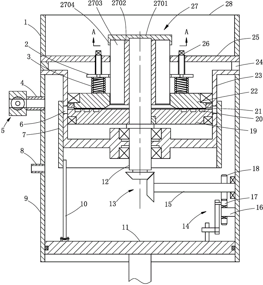
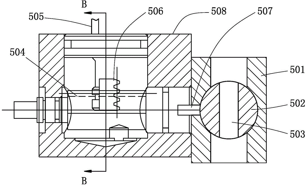
[0030] Such as figure 1 and Figure 4Commonly shown, the present invention provides a plunger pump, including a pump body, the pump body is a straight cylindrical structure, one end of the pump body is provided with a feed port 28, and the other end is slidably installed with a plunger 11, the plunger 11 is connected to drive The unit makes a reciprocating linear motion. A partition wall 25 is provided in the pump body close to the feed port 28. A mounting cylinder 23 is provided in the pump body between the partition wall 25 and the plunger 11. A closed installation is formed ...


PUM


Abstract

The invention discloses a plunger pump and belongs to the technical field of fluid pumps. The plunger pump comprises a pump body, wherein a partition wall is arranged in the pump body close to a material inlet, a mounting barrel is arranged in the pump body between the partition wall and a plunger, and a transmission shaft is rotatably arranged on the mounting barrel. A turntable is fixedly arranged on the transmission shaft in a cavity, a floating plate is arranged between the partition wall and the turntable, an impeller is fixedly arranged on the transmission shaft, and feeding channels are formed between every two adjacent blades. Circulation gaps are formed between the floating plate and the turntable, and a plurality of through holes corresponding to the circulation gaps at positions are formed in the mounting barrel. The transmission shaft penetrates out from one end of the mounting barrel to be connected with the plunger. A sleeve is slidably arranged on the outer surface of the mounting barrel and is connected with the plunger through a connection rod. A material outlet is arranged on the pump body and connected with a ball valve which is controlled by the plunger. The plunger pump solves the technical problems of the existing plunger pump of insufficient suction volume and excessive leakage amount, and is widely applied to continuous fluid transportation.

Description

technical field [0001] The invention relates to a pump, more particularly to a plunger pump, and belongs to the technical field of fluid pumps. Background technique [0002] The plunger pump is an important device of the hydraulic system. It relies on the reciprocating movement of the plunger in the cylinder to change the volume of the sealed working chamber to realize functions such as oil absorption and oil pressure. Because the plunger pump has the advantages of high rated pressure, compact structure, high efficiency and convenient flow adjustment, it is widely used in high pressure, large flow and flow adjustment occasions, such as hydraulic presses, engineering machinery and ships. [0003] The traditional plunger pump is a kind of reciprocating pump, which belongs to the volume pump. Its plunger is driven by the eccentric rotation of the pump shaft to reciprocate, and its suction and discharge valves are check valves. When the plunger is pulled outward, the pressure i...

Claims


Application Information

Patent Timeline
Patent Type & Authority Applications(China)
IPC IPC(8): F04B19/22F04B53/00F04B53/16F04B53/10
Inventor 任贤德
Owner NINGBO LIS IND
Why Eureka
Try Eureka