High-efficiency rotary reciprocating plunger vacuum pump

A high-efficiency, vacuum pump technology, applied in the direction of pumps, multi-stage pumps, pump components, etc., can solve the problems of lower pumping efficiency and unfavorable vacuum degree, and achieve reduced clearance volume, small clearance volume, and low ultimate pressure Effect

Inactive Publication Date: 2015-04-01
付家全
View PDF5 Cites 0 Cited by
  • Summary
  • Abstract
  • Description
  • Claims
  • Application Information

AI Technical Summary

Problems solved by technology

The clearance volume in the pump structure (generally not less than 0.015, refer to the "Complete Book of Technical Standards for Vacuum Equipment Manufacturing Process", Volume 1, Part 4, Chapter 2, Section 2: Reciprocating Vacuum Pumps, Editor-in-Chief: Wang Zhenhua, Ningxia Dadi Audiovisual Publishing House published in 2004), which is not conducive to the improvement of vacuum degree and reduces the actual pumping efficiency of the pump

Method used


Image

  • High-efficiency rotary reciprocating plunger vacuum pump
  • High-efficiency rotary reciprocating plunger vacuum pump
  • High-efficiency rotary reciprocating plunger vacuum pump

Examples


Embodiment Construction

[0018] The present invention will be further described below in conjunction with specific embodiment and accompanying drawing, set forth more details in the following description so as to fully understand the present invention, but the present invention can obviously be implemented in a variety of other ways different from this description, Those skilled in the art can make similar promotions and deductions based on actual application situations without violating the connotation of the present invention, so the content of this specific embodiment should not limit the protection scope of the present invention.

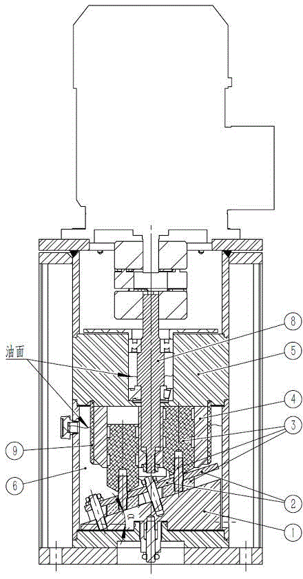
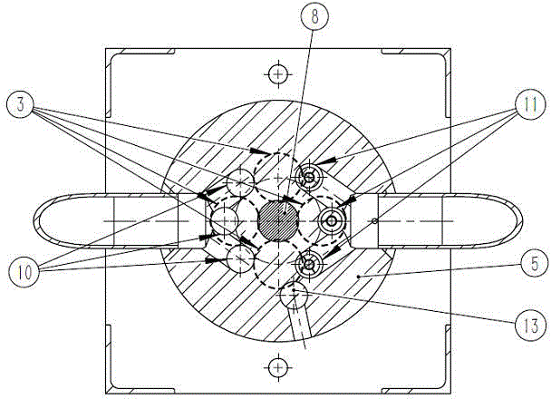
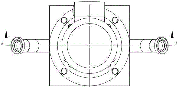
[0019] figure 1 It is a top view of a high-efficiency rotary reciprocating plunger vacuum pump according to an embodiment of the present invention, figure 2 for figure 1 A schematic diagram of the cross-sectional structure of the high-efficiency rotary reciprocating plunger vacuum pump along the line A-A. Such as figure 2 As shown, the high-efficiency rotary recipr...


PUM


Abstract

The invention provides a high-efficiency rotary reciprocating plunger vacuum pump. The vacuum pump comprises a tilting disk, a plunger limiting device, a plunger component, a cylinder body, an air distribution disk, vacuum pump oil, an exhaust valve, an air inlet and an exhaust hole, wherein the cylinder body rotates; the plunger component rotates along the circumferential direction of the cylinder body under the combined action of the tilting disk, the plunger limiting device and the cylinder body and reciprocally moves along the axial direction of the cylinder body; air is sucked from the air inlet through the air distribution disk under the sealing effect of the vacuum pump oil and is discharged from the exhaust hole through an exhaust valve. The reciprocating vacuum pump has the advantages of small clearance volume, high pumping efficiency, low ultimate pressure, capabilities of realizing higher pump limit speed and realizing direct connection with a motor, small size and light weight.

Description

technical field [0001] The invention relates to the technical field of mechanical vacuum pumps, in particular, the invention relates to a reciprocating vacuum pump. Background technique [0002] Existing reciprocating vacuum pumps (refer to "JB / T 7675-2005 Reciprocating Vacuum Pumps") are low-vacuum obtaining equipment. Generally, single-stage pumps can obtain ultimate pressures of 1.3kPa~2.6kPa. The clearance volume in the pump structure (generally not less than 0.015, refer to the "Complete Book of Technical Standards and Specifications for Vacuum Equipment Manufacturing Process", Volume 1, Part 4, Chapter 2, Section 2: Reciprocating Vacuum Pumps, Editor-in-Chief: Wang Zhenhua, Ningxia Dadi Audiovisual Publishing House published in 2004), which is not conducive to the improvement of vacuum degree and reduces the actual pumping efficiency of the pump. In order to ensure that the air valve in the pump structure is closed in time, the pump is limited to run at a lower speed,...

Claims


Application Information

Patent Timeline
Patent Type & Authority Applications(China)
IPC IPC(8): F04B27/20F04B37/14F04B39/10
Inventor 付家全
Owner 付家全
Why Eureka
Try Eureka