
Ball connecting rod, connecting rod assembly and processing method of ball connecting rod

A ball joint connecting rod and connecting rod assembly technology, which is applied in the direction of connecting rod, pivot connection, shaft and bearing, etc., can solve the problems of ball joint and bushing wear, large surface roughness of coating, ball joint and ball socket size Mismatch and other problems, to avoid early failure, high machining accuracy, good fit effect

Active Publication Date: 2015-04-01
GREAT WALL MOTOR CO LTD
View PDF5 Cites 2 Cited by
  • Summary
  • Abstract
  • Description
  • Claims
  • Application Information

AI Technical Summary

Problems solved by technology

The processing sequence of the existing ball-joint connecting rod is the overall electroplating after the blank is cut and formed, because the thickness of the coating layer cannot be accurately controlled in the electroplating process, and the surface roughness of the coating layer is relatively large, which may easily cause a mismatch between the size of the ball head and the ball socket, resulting in a and the double wear of the bushing, eventually leading to early failure and scrapping of the connecting rod assembly

Method used


Image

  • Ball connecting rod, connecting rod assembly and processing method of ball connecting rod
  • Ball connecting rod, connecting rod assembly and processing method of ball connecting rod
  • Ball connecting rod, connecting rod assembly and processing method of ball connecting rod

Examples


Embodiment Construction

[0024] Embodiments of the present invention are described in detail below, examples of which are shown in the drawings, wherein the same or similar reference numerals designate the same or similar elements or elements having the same or similar functions throughout. The embodiments described below by referring to the figures are exemplary only for explaining the present invention and should not be construed as limiting the present invention.

[0025] In the description of the present invention, it should be understood that the terms "first" and "second" are used for description purposes only, and cannot be interpreted as indicating or implying relative importance or implicitly indicating the quantity of indicated technical features. Thus, a feature defined as "first" and "second" may explicitly or implicitly include one or more of these features. In the description of the present invention, "plurality" means two or more, unless otherwise specifically defined.

[0026] In the ...


PUM


Abstract

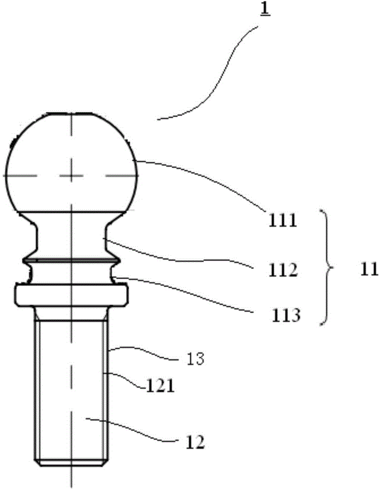
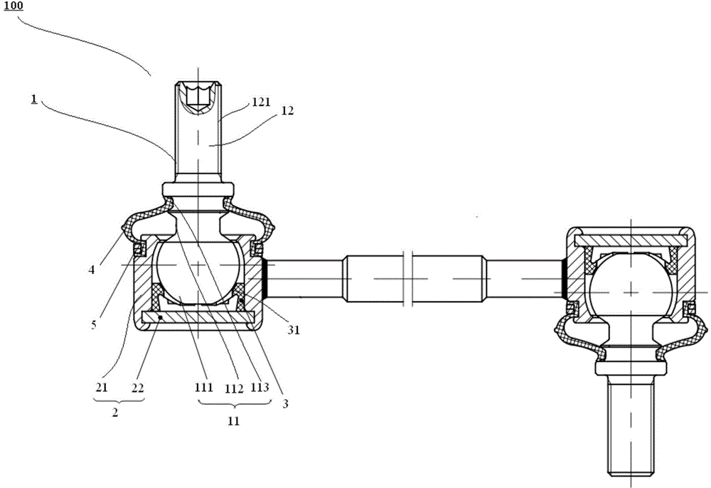
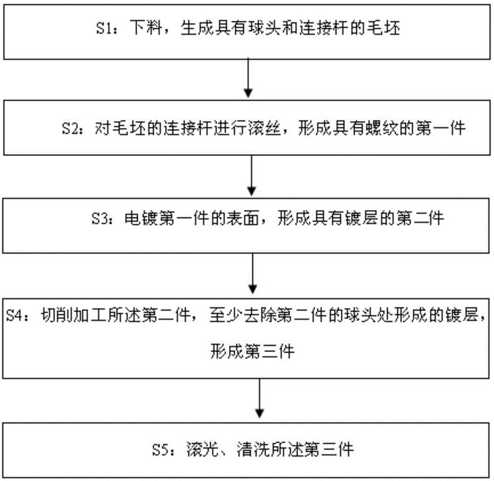
The invention discloses a ball connecting rod, a connecting rod assembly and a processing method of the ball connecting rod. The ball connecting rod is used for matching a ball socket. The ball connecting rod contains a ball which matches the ball socket, a connecting rod which is connected with the ball and has screw thread and a coating which is arranged on the outer surface of the connecting rod and is at least covered with screw thread. The processing method of the ball connecting rod comprises the following steps: S1, blanking is carried out to generate a blank with a ball and a connecting rod; S2, the connecting rod of the blank undergoes thread rolling to form a first part with screw thread; S3, the surface of the first part is electroplated to form a second part with a coating; S4, the second part is cut and processed, and the coating formed at the ball of the second part is at least removed to form a third part; and S5, the third part undergoes barreling and cleaning. According to the ball connecting rod manufactured by the above processing method, the ball has high machining precision and low roughness, the ball matches the ball socket greatly, and early failure of the connecting rod assembly is avoided.

Description

technical field [0001] The invention relates to a connecting rod assembly, in particular to a ball joint rod, a connecting rod assembly and a processing method for the ball joint rod. Background technique [0002] The car connecting rod is an auxiliary elastic component in the car suspension. Ball pins are often used at the connection of the connecting rod. Its function is to prevent excessive lateral roll of the body when turning, prevent the car from laterally tipping and improve ride comfort. sex. Now the main part of the connecting rod assembly is the connecting rod ball pin, and the quality of the ball pin directly affects the service life of the assembly. The processing sequence of the existing ball-joint connecting rod is the overall electroplating after the blank is cut and formed, because the thickness of the coating layer cannot be accurately controlled in the electroplating process, and the surface roughness of the coating layer is relatively large, which may eas...

Claims


Application Information

Patent Timeline
Patent Type & Authority Applications(China)
IPC IPC(8): F16C7/02F16C11/06B23P15/14
Inventor 刘新芳贾贺
Owner GREAT WALL MOTOR CO LTD
Learn More