Pulse amplitude measurement circuit and method capable of reducing counting losses

A technology of pulse amplitude and count loss, which is applied in the field of nuclear pulse signal amplitude measurement, can solve the problems of difficult increase of count rate and count loss, and achieve the effects of fast speed, improved processing capacity and high precision

Active Publication Date: 2015-04-01
UNIV OF SCI & TECH OF CHINA
View PDF6 Cites 18 Cited by
  • Summary
  • Abstract
  • Description
  • Claims
  • Application Information

AI Technical Summary

Problems solved by technology

Tail accumulation will cause the amplitude of the next pulse to be distorted, so the usual processing method is to retain the information of the previous pea

Method used


Image

  • Pulse amplitude measurement circuit and method capable of reducing counting losses
  • Pulse amplitude measurement circuit and method capable of reducing counting losses
  • Pulse amplitude measurement circuit and method capable of reducing counting losses

Examples


Embodiment 1

[0061] Figure 4 It is a schematic diagram of a pulse amplitude measurement circuit for reducing count loss provided by Embodiment 1 of the present invention. like Figure 4 As shown, the circuit mainly includes: forming amplifier circuit, high-speed AD conversion circuit, fast peak-seeking and discharge control circuit, and signal fast recovery circuit;

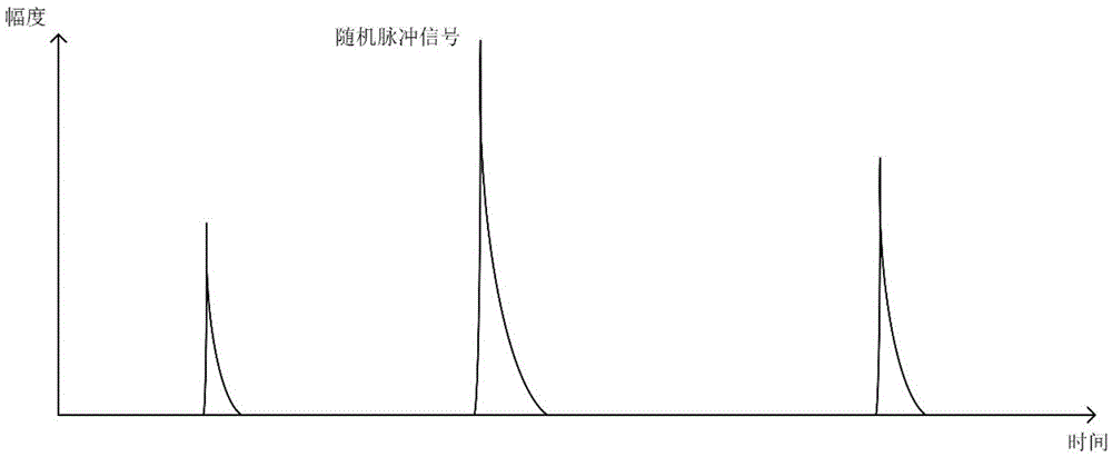
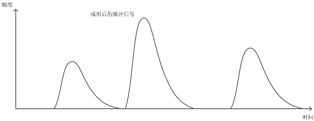
[0062] Wherein, the shaping amplifier circuit is used to expand the random pulse signal output by the nuclear detector into a pulse shape with a flat top that is convenient for amplitude measurement, and amplify the signal amplitude before outputting;

[0063] The high-speed AD conversion circuit is used to continuously sample the pulse signal output by the forming amplifier circuit and convert it into a digital quantity for output;

[0064] The fast peak-seeking and discharge control circuit is used to calculate the amplitude of the digital signal waveform output by the high-speed AD conversion circuit, store it after the...

Embodiment 2

[0086] An embodiment of the present invention provides a pulse amplitude measurement method that reduces count loss, and the method can be implemented based on the circuit described in the first embodiment. Such as Figure 9 As shown, it mainly includes:

[0087] Step 91: The random pulse signal output by the nuclear detector is broadened by the shaping and amplifying circuit into a pulse shape with a flat top that is convenient for amplitude measurement, and the signal amplitude is amplified before outputting.

[0088] Step 92: The high-speed AD conversion circuit performs continuous sampling on the pulse signal output by the shaping amplifier circuit and outputs it after conversion.

[0089] Step 93: Perform amplitude calculation on the digital signal waveform output by the high-speed AD conversion circuit by the fast peak-seeking and discharge control circuit, store after the amplitude calculation is completed, and output a discharge control signal to the signal fast recov...


PUM


Abstract

The invention discloses a pulse amplitude measurement circuit and method capable of reducing counting losses. Related circuits comprise a forming and amplifying circuit, a high-speed AD (analog-to-digital) conversion circuit, a quick peak searching and discharging control circuit and a signal fast-recovery circuit, wherein the forming and amplifying circuit is used for widening and forming random pulse signals output by a nuclear detector into pulse shapes which have flat tops and can facilitate amplitude measurement and outputting the signal amplitude after amplifying the signal amplitude; the high-speed AD conversion circuit is used for continuously sampling pulse signals output by the forming and amplifying circuit, converting the pulse signals into digital quantities and then outputting the digital quantities; the quick peak searching and discharging control circuit is used for performing amplitude calculation on waveforms of digital signals output by the high-speed AD conversion circuit, performing storage after amplitude calculation is finished, and outputting discharging control signals to the signal fast-recovery circuit; the signal fast-recovery circuit is used for performing control according to the received discharging control signals and recovering the amplitude of pulses output by the forming and amplifying circuit to the base line level. With the adoption of the circuit and the method, counting rate losses caused by the stacking effect of nuclear pulse signals under the condition of the high counting rate can be reduced, and the circuit is simple and reliable in structure and convenient to popularize.

Description

technical field [0001] The invention relates to the technical field of nuclear pulse signal amplitude measurement, in particular to a pulse amplitude measurement circuit and method for reducing count loss. Background technique [0002] The pulse amplitude measurement method of the digitized nuclear pulse signal is to first shape and amplify the signal, then continuously sample the signal through the ADC (Analog-to-Digital Converter), and then digitize the sampled data through logic devices such as FPGA (Field Programmable Gate Array) The amplitude of the pulse signal is obtained by peak-seeking processing; and then the random signal is counted and accumulated according to different amplitude values ​​to obtain the amplitude spectrum of the random pulse signal. The more precise the amplitude measurement, the higher the resolution of the amplitude spectrum. The higher the occurrence frequency of the random pulse signal, the higher the average count rate of the measurement, th...

Claims


Application Information

Patent Timeline
IPC IPC(8): G01R29/02
Inventor 陈炼刘宇哲梁福田李锋金革
Owner UNIV OF SCI & TECH OF CHINA
Why Eureka
Try Eureka