
An automatic control device for a building communication cabinet

A technology of automatic control devices and cabinets, applied in general control systems, program control, comprehensive factory control, etc., can solve problems such as waste of electric energy, power failure, and poor contact equipment.

Inactive Publication Date: 2017-10-13
SUZHOU SUNGO TECH
View PDF5 Cites 0 Cited by
  • Summary
  • Abstract
  • Description
  • Claims
  • Application Information

AI Technical Summary

Problems solved by technology

[0003] (1) The equipment in the weak current room is randomly placed inside and outside the cabinet, lacking unified management;
[0004] (2) The strong and weak wires in the cabinet are seriously intersected, and there is no unified standard for power distribution, which may easily lead to poor contact or leakage and cause power failure of the equipment;
[0005] (3) The wiring in the cabinet is mixed, power lines and signal lines, high-frequency lines and low-frequency lines, digital lines and analog lines cross each other, which is prone to serious inter-line interference problems;
[0006] (4) The cabinet equipment is scattered in various weak current rooms. If the equipment fails, the root cause of the problem cannot be quickly located, and the efficiency is low;
[0007] (5) The heat dissipation equipment in the cabinet cannot be started and stopped according to the actual temperature in the weak current room, which leads to a waste of power when it is not needed to be turned on, or when it needs to be turned on, the temperature in the cabinet is too high and the equipment is damaged;
[0008] (6) The current and voltage are unstable, which may easily lead to equipment damage;

Method used


Image

  • An automatic control device for a building communication cabinet
  • An automatic control device for a building communication cabinet
  • An automatic control device for a building communication cabinet

Examples


Embodiment

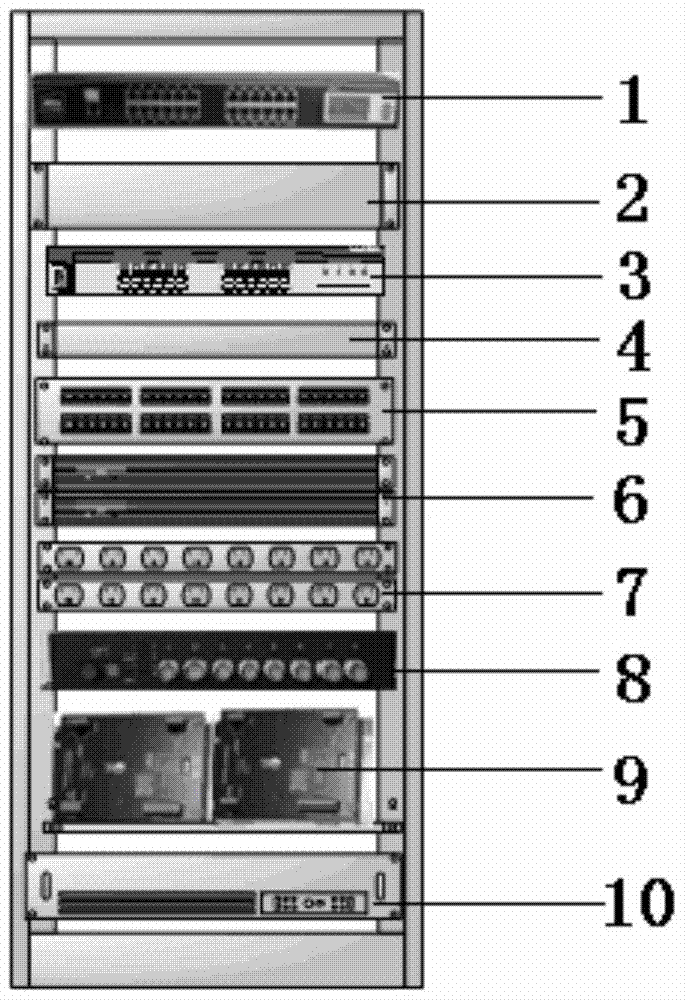
[0027] An automatic control device for building communication cabinets, the cabinet body is made of high-quality cold-rolled steel plates, the thickness of the cabinet column is 2.0mm, the thickness of the side panels and front and rear doors is 1.2mm, and the thickness of the fixed tray is 1.2mm, ensuring that the cabinet load bearing. Such as figure 1 Shown is the layout of the equipment in the cabinet. Inside the cabinet, there are intelligent manager 1, power distribution box 2, switch 3, cable management frame 4, distribution frame 5, optical fiber distribution frame 6, PDU7, optical transceiver 8, access controller 9, and set The UPS at the bottom of the box and its supporting power supply 10; the ports of the distribution frame 5 and the fiber distribution frame 6 are managed by electronic labels, and the ports of the switch 3 and optical transceiver 4 are also managed by electronic labels. The electronic label controllers are respectively connected with the intelligen...


PUM


Abstract

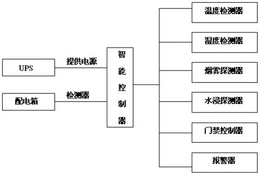
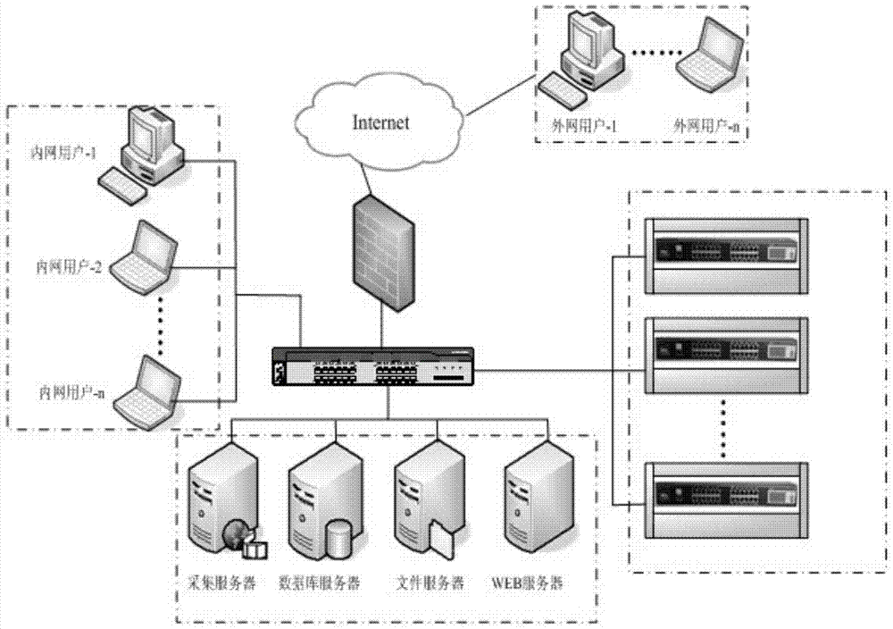
The invention discloses a building communication cabinet automatic control device which comprises a cabinet. The cabinet is internally and fixedly provided with an intelligent controller, a power distribution box, a switch, a wire arrangement frame, a distribution frame, a fibre distribution frame, a PDU, an optical transceiver, an access controller and a UPS and matching power source thereof from the top down in sequence by means of trays. The power distribution box is electrically connected with the intelligent controller through a current and voltage detector. The cabinet is further internally provided with a temperature detector, a humidity detector, a smog detector, a water logging detector and an alarm, which, together with the access controller, are electrically connected with the intelligent controller. The intelligent controller is connected with a remote monitoring system terminal through a network. The cabinet of the device is in standard design; port and device installation are increased and added as needed; sufficient redundancy design is realized; different devices are in subarea arrangement in structure; the distribution frame and the wire arrangement frame are made full use of; and therefore, anti-interference between wires is realized, the cabinet realizes UPS integrated self-powering; and the cabinets in the network are interconnected through the intelligent controller, and intelligent centralized management is realized.

Description

technical field [0001] The invention relates to a monitoring device for a building communication cabinet, more specifically, to an automatic control and remote monitoring device for a building communication cabinet. Background technique [0002] According to the current building's higher and higher requirements for intelligence, the system equipment is becoming more and more complex, and the implementation of the entire building's intelligence and post-management are also facing greater challenges, especially for unattended floors with weak electricity. For the management of the equipment, due to the lack of unified specifications and corresponding monitoring and management methods, a large number of problems have emerged: [0003] (1) The equipment in the weak current room is randomly placed inside and outside the cabinet, lacking unified management; [0004] (2) The strong and weak wires in the cabinet are seriously intersected, and there is no unified standard for power ...

Claims


Application Information

Patent Timeline
Patent Type & Authority Patents(China)
IPC IPC(8): G05B19/418
CPCG05B19/41835
Inventor 高艳辉孙向东杨俊
Owner SUZHOU SUNGO TECH
Learn More