Satellite borne electronic system capable of being debugged on orbit and on-orbit debugging method

An electronic system, on-board technology, applied in the field of satellite on-board electronics, to achieve the effect of facilitating the discovery of problems and locating problems

Active Publication Date: 2015-04-01
AEROSPACE DONGFANGHONG DEV LTD
View PDF6 Cites 8 Cited by
  • Summary
  • Abstract
  • Description
  • Claims
  • Application Information

AI Technical Summary

Problems solved by technology

[0007] In order to overcome the deficiencies of the existing technology, the present invention provides an on-orbit debugging on-board electronic system, which can quickly locate CPU internal problems and some system problems

Method used


Image

  • Satellite borne electronic system capable of being debugged on orbit and on-orbit debugging method
  • Satellite borne electronic system capable of being debugged on orbit and on-orbit debugging method

Examples


Embodiment Construction

[0020] The present invention will be further described below in conjunction with the accompanying drawings and specific embodiments.

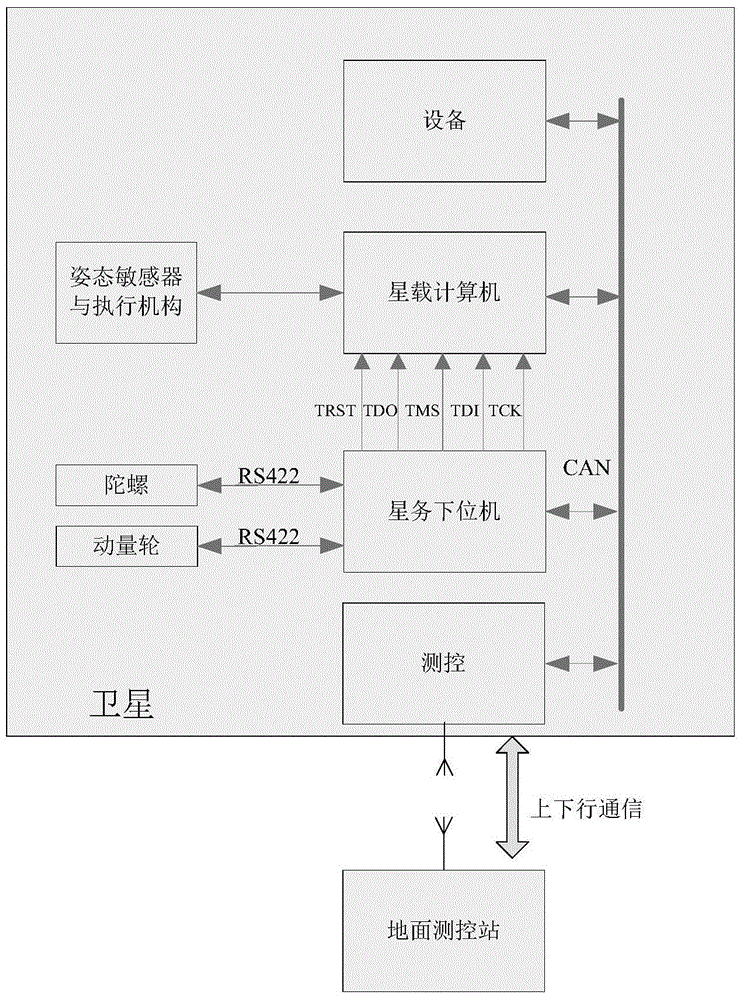
[0021] as attached figure 1 As shown, the on-orbit debugging on-board electronic system of the present invention includes an on-board computer and a satellite slave computer; the satellite slave computer is also connected to the on-board CAN bus and attitude control components (to ensure the basic sun-facing attitude); The satellite lower computer FPGA debugs the onboard computer CPU through the JTAG interface, sends various control commands to the onboard computer CPU through the ground uplink channel, and transmits the CPU internal register and external memory status through the satellite downlink channel. JTAG (Joint Test Action Group; Joint Test Working Group) technology is an embedded debugging technology that can test the electrical characteristics of the chip and detect whether there is a problem with the chip. The JTAG interface includ...


PUM


Abstract

The invention provides a satellite borne electronic system capable of being debugged on an orbit and an on-orbit debugging method. In a debugging mode, a satellite lower computer FPGA (Field Programmable Gate Array) carries out debug on a CPU (Central Processing Unit) of a satellite borne computer by a JTAG (Joint Test Action Group) interface; a satellite sends various control commands to the CPU by an uplink channel and transmits states of an internal register and an external storage of the CPU by a downlink channel; the satellite lower computer replaces attitude control and bus management functions of the satellite borne computer and normal work of the satellite is not influenced in the debugging process, so the system can carry out complete replacement on an original program of the satellite borne computer instead of partial replacement, data of the internal register and the external storage can be directly viewed by the commands, problems are convenient to find and position, on-orbit single-step debugging can be carried out and in the debugging process, values can be forcedly assigned to related registers or memories so as to assist in rapid positioning of faults.

Description

technical field [0001] The invention belongs to the technical field of satellite on-board electronics, in particular to an on-orbit debugging on-board electronic system. Background technique [0002] On the one hand, with the requirement of rapid response to satellites, the satellite system needs to be deployed to the designated orbit as quickly as possible, and the development time of the on-board electronic system on the ground is shortened, and the electronic system needs to be capable of on-orbit debugging. On the other hand, the main missions of some in-orbit satellites have been completed, and new missions can be deployed through on-orbit code update and debugging. [0003] In order to adapt to different mission requirements and deal with various sudden failures, on-orbit debugging and updating of the on-orbit electronic system software is required. [0004] At present, the common way is to add some new codes to cover the old codes or add new codes, and directly repla...

Claims


Application Information

Patent Timeline
Patent Type & Authority Applications(China)
IPC IPC(8): G06F11/36
Inventor 蒲卫华黄维达柯广贤吴志远何波
Owner AEROSPACE DONGFANGHONG DEV LTD
Why Eureka
Try Eureka