Moving plunger for gas well production with water withdrawal

A drainage gas recovery and plunger technology, which is applied in the direction of mining fluids, earth drilling, machines/engines, etc., can solve the problems of high cost and complicated operation methods, achieve long service life, good effect, and maintain long-term self-spraying production Effect

Inactive Publication Date: 2015-04-08
BEIJING JINKELONG PETROLEUM TECH DEV
View PDF9 Cites 7 Cited by
  • Summary
  • Abstract
  • Description
  • Claims
  • Application Information

AI Technical Summary

Problems solved by technology

The above-mentioned technological measures are more restricted by well conditions and mining conditions, the operation method is complicated, and the cost is also high

Method used


Image

  • Moving plunger for gas well production with water withdrawal

Examples


Embodiment Construction

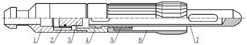
[0009] Such as figure 1 As shown, the swimming plunger for drainage and gas recovery of the present invention includes a fishing head 1, a sealing rod 3 located in the fishing head 1, a retaining sleeve 2 is arranged between the fishing head 1 and the sealing rod 3, and the retaining The sleeve 2 is used to limit the movement range of the sealing rod 3; the outer sleeve 4 is threadedly connected to the lower part of the fishing head 1, and the impact rod 7 is movable inside the outer sleeve 4; the outer sleeve of the outer sleeve 4 is covered with an elastic seal Claw 6.

[0010] One end of the outer sleeve 4 is threadedly connected with a fixing sleeve 5 , and the fixing sleeve 5 is used for fixing the elastic sealing jaw 6 on the outer sleeve 4 .

[0011] The working principle of the swimming plunger for drainage and gas recovery of the present invention:

[0012] The elastic sealing claw of the swimming plunger for drainage and gas recovery of the present invention is an ...


PUM


Abstract

The present invention provides a moving plunger for gas well production with water withdrawal which is simple in structure and good in accumulated fluid withdrawal effect. The moving plunger comprises a fish head, a sealing rod in the fish head, a retaining sleeve which is arranged between the fish head and the sealing rod and used for limiting the movement range of the sealing rod, wherein the lower part of the fish head is screwedly connected with an outer sleeve, a drop bar is movably arranged in the outer sleeve; and the outer part of the outer sleeve is sleeved with an elastic sealing claw. The tool vertically floats due to the pressure in well, so that the shaft accumulated fluid is lifted and discharged through a well opening, and finally natural gas is developed or water flooding of other gas wells in the same air reservoir is delayed and avoided, so as to improve the production state of the whole air reservoir and increase the final production rate of the air reservoir. The moving plunger has features of simple structure, good accumulated fluid withdrawal effect, long service life, and achieves the purpose of gas production and yield increase.

Description

technical field [0001] The invention relates to a device for drainage and gas production, in particular to a swimming plunger for drainage and gas production. Background technique [0002] In the initial stage of natural gas well development, due to the high energy of the gas layer, the natural gas and produced liquid can be lifted to the ground by the energy of the gas well itself, so that there will be no liquid accumulation. However, as mining continues to enter the middle and late stages year by year, the formation energy continues to decline, the formation water output increases year by year, and the liquid-carrying capacity of the produced gas decreases, so that the gas cannot carry all the liquid, resulting in gradual liquid accumulation in the wellbore. With the rise of the liquid level, the bottom hole pressure will increase and the gas production will further decrease. If the liquid accumulation cannot be discharged in time and effectively, a large amount of liquid...

Claims


Application Information

Patent Timeline
Patent Type & Authority Applications(China)
IPC IPC(8): E21B43/34F04B47/12
CPCF04B47/00F04B53/14
Inventor 周晓东任丽琴陈志强周艳秀周旭清
Owner BEIJING JINKELONG PETROLEUM TECH DEV
Why Eureka
Try Eureka