Tuned mass damper for vibration-damping experiment of structure model and design method

A tuned mass damping and vibration reduction test technology, which is applied to springs/shock absorbers, mechanical equipment, magnetic springs, etc., can solve the problems of TMD, such as difficult adjustment of damping parameters, inability to provide quantitative decision-making reference for vibration reduction optimization design, etc., to achieve The inherent damping is small, the effect of reducing magnetic circuit loss and improving work efficiency

Active Publication Date: 2015-04-08
NORTH CHINA UNIV OF WATER RESOURCES & ELECTRIC POWER
View PDF9 Cites 12 Cited by
  • Summary
  • Abstract
  • Description
  • Claims
  • Application Information

AI Technical Summary

Problems solved by technology

[0011] According to the present invention, it is difficult to accurately adjust the optimal damping parameters required by the TMD vibration reduction test for the existing structural model vibration reduction test, which leads to the structural model TMD vibration reduction test can only play a qualitative demonstration of the TMD vibration reduction effect, and cannot truly provide The vibration reduction optimization design of TMD provides quantitative decision-making reference, and issues such as vertical and horizontal TMD need to be made separately, provide a simple and adjustable damping parameter, damping and stiffness parameters are completely separated, and at the same time satisfy the structural model horizontal or vertical Tuned mass damper setup required for vibration damping tests

Method used


Image

  • Tuned mass damper for vibration-damping experiment of structure model and design method
  • Tuned mass damper for vibration-damping experiment of structure model and design method
  • Tuned mass damper for vibration-damping experiment of structure model and design method

Examples


Embodiment Construction

[0034] Below in conjunction with accompanying drawing, the present invention will be described in further detail with regard to preferred embodiment:

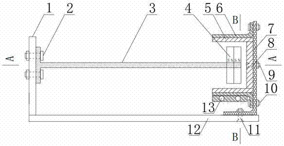
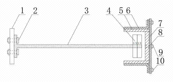
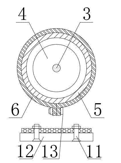
[0035] see figure 1 , figure 2 , image 3 , a tuned mass damper for two-way vibration reduction tests of structural models, including a bottom plate 12, a vertical plate 1, a mass block, an elastic element, an energy dissipation element, and a support device for fixing the energy dissipation element, and the vertical plate 1 is fixed on One end of the bottom plate 12 and the other end of the bottom plate 12 are fixed with a supporting device, the supporting device adopts angle steel 7, and there are two waist-shaped holes at the bottom of the angle steel 7, which are connected with the bottom plate through countersunk head bolts and nuts 11 to realize the horizontal movement of the angle steel on the bottom plate, and the elastic The component adopts a cantilever beam 3, which is made of a solid aluminum rod with a small ela...


PUM


Abstract

The invention discloses a tuned mass damper (TMD) for the vibration-damping experiment of a structure model. The tuned mass damper comprises a mass block, an elastic element, an energy dissipation element and a support angle bar, wherein the mass block adopts ring permanent magnets and small iron blocks adsorbed on the ring permanent magnets; the elastic element adopts a horizontal aluminum bar cantilever beam structure; the energy dissipation element adopts electromagnetic damping, when the mass block is horizontally or vertically vibrated, a copper plate and a copper tube which are mounted on the support angle bar cut a magnetic induction line generated by the moving permanent magnets, and structural vibrating energy is gradually converted into heat energy to be consumed. According to the invention, through unique structural design, the TMD can satisfy the requirements of the structure model for the vibration-damping experiment in the horizontal direction and in the vertical direction at the same time; the permanent magnets required by the energy dissipation element are directly used as the mass block of the TMD, and the structure is compact; the damping parameter and the frequency parameter of the TMD are completely separated, and quantification regulation can be made, so that precise simulation for the excellent damping parameter of the TMD for in the vibration-damping experiment of the structure model in the horizontal direction or the vertical direction can be realized.

Description

technical field [0001] The invention belongs to the technical field of civil engineering structure tests, and in particular relates to a tuned mass damper and a design method for structural model vibration reduction tests. Background technique [0002] The tuning mass damper (TMD) vibration reduction design of large buildings (long-span bridges, high-rise structures, etc.) often requires the vibration reduction test of the structural model to optimize the selection of TMD parameters and verify the vibration reduction effect. The characteristics of the TMD required for the structural model vibration reduction test are high frequency (generally between 6 and 15Hz, mainly related to the geometric scale ratio of the structural model), and small mass (generally between 0.2 and 3Kg, mainly related to the structural model’s Geometric scale ratio and mass ratio of TMD vibration damping design), although TMD vibration damping technology has been widely used in practical engineering, ...

Claims


Application Information

Patent Timeline
Patent Type & Authority Applications(China)
IPC IPC(8): F16F6/00
CPCF16F6/005
Inventor 汪志昊陈政清华旭刚王玉柱贾美晨
Owner NORTH CHINA UNIV OF WATER RESOURCES & ELECTRIC POWER
Why Eureka
Try Eureka