
Reservoir culvert detection robot

A technology of robots and culvert pipes, which is applied in the direction of special pipes, pipe components, mechanical equipment, etc., can solve the problems that are not suitable for the working environment of reservoir culvert pipes, difficult to adjust the posture of pipes, and large mechanical structure size, etc., to achieve light weight, compact structure, and changeable powerful effect

Active Publication Date: 2015-04-08
广东智慧水云科技有限责任公司
View PDF5 Cites 46 Cited by
  • Summary
  • Abstract
  • Description
  • Claims
  • Application Information

AI Technical Summary

Problems solved by technology

[0008] The spiral-driven pipeline robot is usually composed of a stationary part and a rotating part. Each wheel of the rotating part has an included angle with the pipe wall. Relying on the rotation of the robot's rotating part, each roller will spiral up along the pipe wall, thereby driving the stationary part to move along the axis of the pipe wall. , since the rollers of the rotating part spiral up along the pipe wall, obstacles encountered on the spiral path cannot be avoided, so the barrier ability is poor, and it is not suitable for reservoir culvert pipes
[0009] The crawler-type pipeline robot relies on the crawler to move in the pipeline. Although the crawler has strong adhesion and has superior obstacle-surpassing ability, the driving mechanism is complicated, the mechanical structure is large, and it is difficult to adjust the posture in the pipeline. It is not suitable for the working environment of the reservoir culvert.

Method used


Image

  • Reservoir culvert detection robot
  • Reservoir culvert detection robot
  • Reservoir culvert detection robot

Examples


Embodiment Construction

[0036] The present invention will be further described below in conjunction with the accompanying drawings and embodiments.

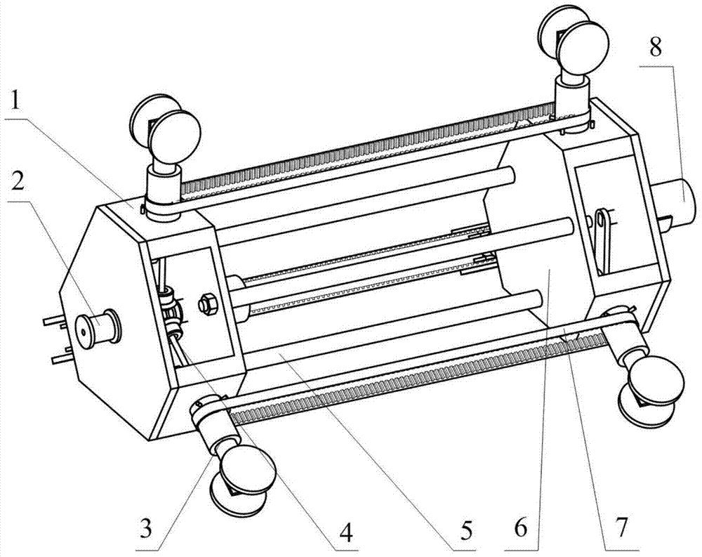
[0037] Such as figure 1 As shown, the reservoir culvert inspection robot includes a driving wheel set 1, a steering system 2, a connecting mechanism 5, a driven wheel set 6, a synchronous belt 7 and a control system 8; the driving wheel set 1 and the driven wheel set 6 are connected through the connecting mechanism 5, The steering system 2 controls the steering of the drive wheel set 1 .

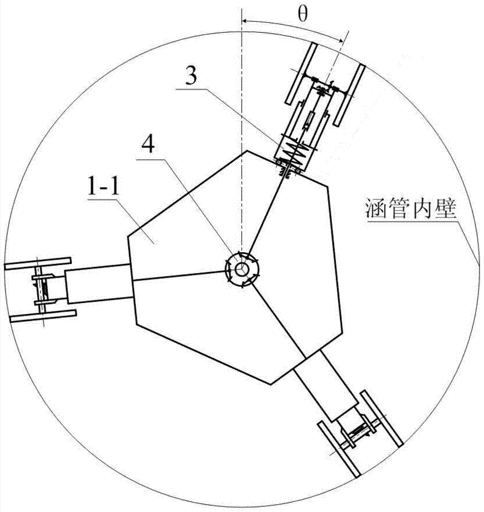
[0038] Such asfigure 1 and 2 As shown, the drive wheel set 1 includes a first main mounting plate 1-1, a wheel-leg mechanism 3 and a transfer system 4; the three wheel-leg mechanisms 3 are uniformly arranged on the side wall of the first main mounting plate 1-1 along the circumference Above; the transfer system 4 is arranged at the center of the first main mounting plate 1-1 to drive the three wheel-leg mechanisms 3 .

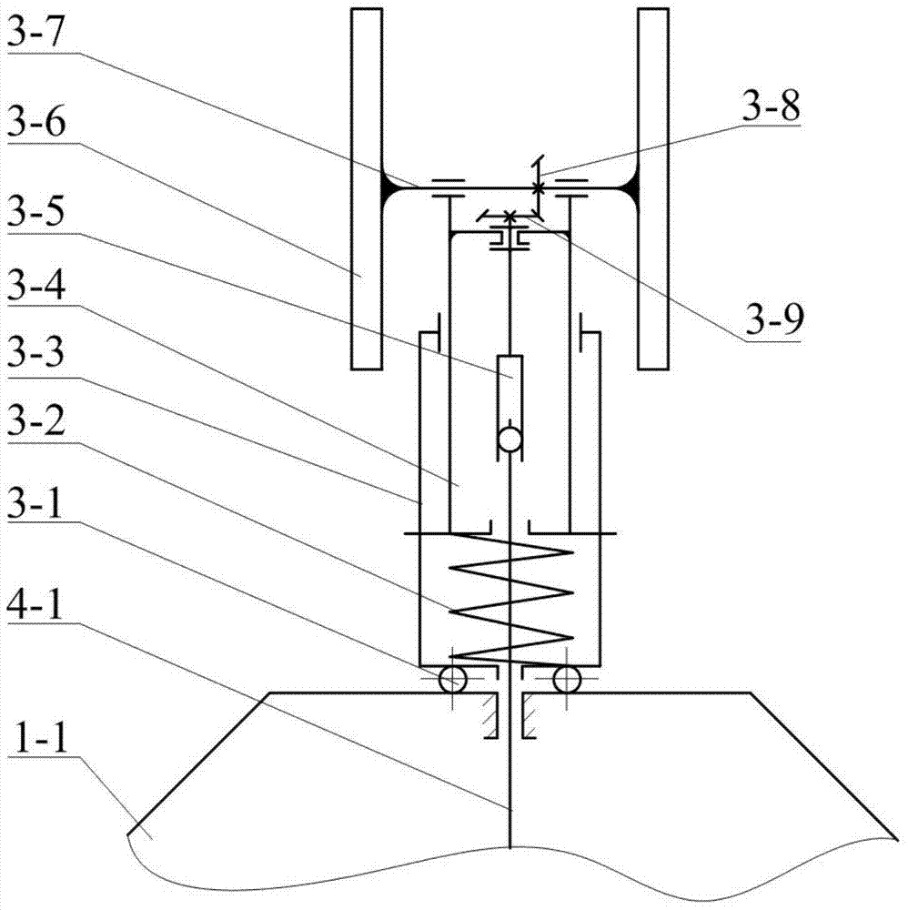
[0039] Such as figure 2 and 3 As shown, th...


PUM


Abstract

The invention discloses a reservoir culvert detection robot. A special pipeline robot aiming at the reservoir culvert detection work is not designed in the prior art. The reservoir culvert detection robot comprises a driving wheel group, a steering system, a connecting mechanism, a driven wheel group and a control system, wherein the driving wheel group and the driven wheel group are connected through the connecting mechanism, the steering system controls the steering of the driving wheel group, the driving wheel group comprises wheel leg mechanisms and a transfer system, the three wheel leg mechanisms are uniformly distributed and arranged on the side wall of a first main installing plate, the transfer system is arranged in the center part of the first main installing plate, and drives the three wheel leg mechanisms, and the steering system comprises a rope, a steering rope roller, a steering motor, a steering reset spring, an initial position stop pin, a pull arm and a terminal position stop pin. The reservoir culvert detection robot is suitable for the work environment of a reservoir culvert, and can do autoroatation around the pipeline center in situ in the pipeline for avoiding obstacles; two rows of wheel groups including the front row and the back row and a telescopic diameter change mechanism are adopted, the telescopic quantity of each wheel leg is respectively independent, and the pipeline diameter change adapting capability is high.

Description

technical field [0001] The invention belongs to the field of machinery, and relates to a pipeline robot, in particular to a reservoir culvert pipe detection robot. Background technique [0002] As a convenient and effective material transportation tool, pipelines are widely used in daily life. During the long-term use of pipelines, it is inevitable that there will be cracks and leakage, especially in reservoir culvert pipes. Once problems occur, the consequences of reservoir dam accidents will be very serious. The diameter of the reservoir culvert pipe is relatively small, there are no branch roads, there will be moss and other objects on the inner wall of the culvert pipe, and there will be water and silt at the bottom, accompanied by gravel, pits and other obstacles, and personnel cannot directly enter. The inspection of the reservoir culvert pipe is a very difficult thing. Only the pipeline robot can be used for efficient detection, and the detection of reservoir culver...

Claims


Application Information

Patent Timeline
Patent Type & Authority Applications(China)
IPC IPC(8): F16L55/32F16L101/30
CPCF16L55/32
Inventor 夏旭东陈建能徐高欢肖达度
Owner 广东智慧水云科技有限责任公司
Learn More