Jet flow heat radiationmechanism and jet flow heat radiator

A heat dissipation mechanism and heat sink technology, which is applied in the field of jet heat dissipation mechanism, heat dissipation mechanism, and jet heat sink, can solve the problems of poor effect, achieve good effect, prevent damage, and reduce noise

Active Publication Date: 2015-04-08
李达
View PDF6 Cites 2 Cited by
  • Summary
  • Abstract
  • Description
  • Claims
  • Application Information

AI Technical Summary

Problems solved by technology

That is, it uses heat conduction to dissipate heat from the heat source, but does not really use the jet flow generated by the air to dissipate heat from the heat source. This heat dissipation method can also be used for small equipment, but its effect is barely enough for larger equipment and cannot meet the actual needs. needs

Method used


Image

  • Jet flow heat radiationmechanism and jet flow heat radiator
  • Jet flow heat radiationmechanism and jet flow heat radiator
  • Jet flow heat radiationmechanism and jet flow heat radiator

Examples


Embodiment

[0037] Embodiment A jet cooling mechanism

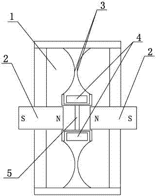
[0038] This embodiment is a jet cooling mechanism, such as figure 1 As shown, it includes:

[0039] The cavity 1 composed of the outer casing and the diaphragm is fixed with two magnets 2 arranged at intervals in the cavity 1. In this embodiment, a permanent magnet is used, and the two magnetic poles of the two magnets 2 have the same polarity. Relative setting, that is, the N poles of the two magnets are set oppositely, or the S poles of the two magnets are set oppositely. An electromagnet mechanism is arranged between the two magnets, and the electromagnet mechanism can move towards any magnet 2 under the action of the magnetic force of the two magnets 2. The tympanic membrane 3 is fixed on the electromagnetic mechanism, and the cavity 1 A first air port and a second air port connecting the cavity with the outside are also provided on the top.

[0040]Described electromagnetic mechanism comprises the electromagnet 4 that magneti...


PUM


Abstract

The invention discloses a jet flow heat radiation mechanism and a jet flow heat radiator. The jet flow heat radiation mechanism comprises a cavity consisting of an outer shell and a diaphragm, wherein two magnets are fixedly arranged in the cavity at an interval; two magnetic poles with the same magnetism, of the two magnets, are arranged oppositely; an electromagnetic mechanism is arranged between the two magnets; the electromagnetic mechanism can move towards any magnet under the action of the magnetism of the two magnets; a tympanic membrane is fixedly arranged on the electromagnetic mechanism; a first air outlet and a second air outlet for connecting the cavity with the outside are formed in the cavity. The jet flow heat radiation mechanism is simple in structure, low in energy consumption, good in heat radiation effect and low in noise, and is applicable to heat radiators or heat resources of which the heat needs to be radiated. The jet flow heat radiation mechanism is applicable to heat radiation of heat radiators or heat sources of any shape or any size.

Description

technical field [0001] The invention belongs to the field of heat dissipation, and relates to a heat dissipation mechanism, specifically a jet heat dissipation mechanism; meanwhile, the invention also provides a jet radiator composed of the jet heat dissipation mechanism. Background technique [0002] Many devices in the prior art need to be equipped with radiators to perform heat dissipation treatment on the devices to ensure good performance of the devices. Most of the heat sinks used in the prior art use fans to dissipate heat. However, if the fan runs for a long time, especially outdoors for a long time, it will be affected by dust and other sundries in the air, reducing its heat dissipation performance. At the same time, the effect of using fans for heat dissipation is not good. For example, when cooling large-scale equipment, larger fans are needed to meet the heat dissipation requirements. The increase in fan volume not only complicates the structure and production pr...

Claims


Application Information

Patent Timeline
Patent Type & Authority Applications(China)
IPC IPC(8): F28F13/02F28F13/12
Inventor 李达
Owner 李达
Why Eureka
Try Eureka