
Detection and diagnosis method for battery charge and battery health state

A battery health status and detection method technology, applied in the direction of measuring electrical variables, measuring electricity, measuring devices, etc., can solve the problems that the level of evaluation is not deep enough, fast, non-destructive testing, and essence cannot be analyzed

Active Publication Date: 2015-04-08
SHENZHEN GRADUATE SCHOOL TSINGHUA UNIV
View PDF7 Cites 52 Cited by
  • Summary
  • Abstract
  • Description
  • Claims
  • Application Information

AI Technical Summary

Problems solved by technology

[0006] In short, the existing battery SOH evaluation has the following disadvantages: the detection process is complex and time-consuming, and the time and labor costs are huge; the evaluation level is not deep enough, and it can only describe the appearance but not the essence; it cannot achieve fast and non-destructive testing.

Method used


Image

  • Detection and diagnosis method for battery charge and battery health state
  • Detection and diagnosis method for battery charge and battery health state
  • Detection and diagnosis method for battery charge and battery health state

Examples


Embodiment 1

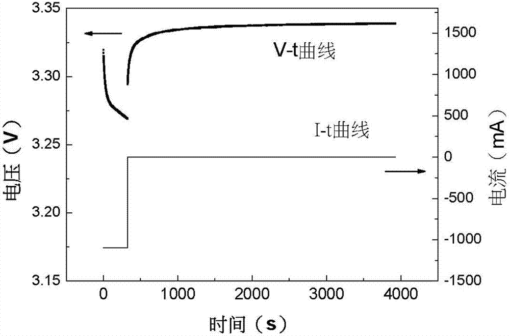
[0073] Please refer to Figure 3~6 .

[0074] Example 1 provides a 18650-type lithium iron phosphate / graphite power battery cell with a rated capacity of 1.1 Ah, and detects the SOH of the battery. The charge and discharge cut-off voltage range of the battery is 2.5~3.65V. The working environment of the battery is a constant temperature environment of 45°C. The current state of the battery is: under the working state of cyclic charging and discharging with 1C current constant current and constant voltage of nominal capacity - shelving - constant current discharge with 1C current of nominal capacity, the battery has been charged and discharged 50 times.

[0075] Step 1: Test the capacity C of the battery, and then place the battery until the voltage at both ends returns to a stable value. Place the battery in an environment of 25°C, charge it to 3.65V at a constant current with a nominal capacity of 1C, and then discharge it to 2.5V at a constant current with a nominal capac...

Embodiment 2

[0086] Please refer to Figure 8~12 .

[0087] Example 2 provides a soft-pack type lithium iron phosphate / graphite power battery cell with a rated capacity of 1.1 Ah, and detects the SOH of the battery. The charge and discharge cut-off voltage range of the battery is 2.5~3.65V. The battery was left for a month at 25°C and 20% SOC.

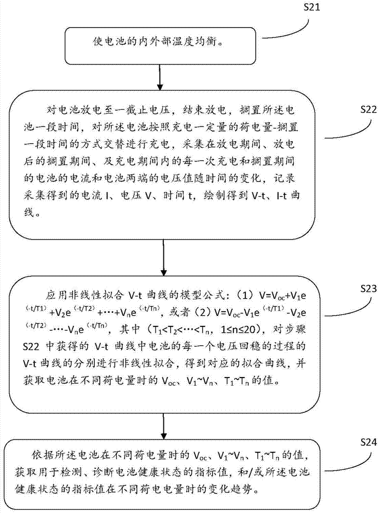
[0088] Step 1, the battery is placed in a constant temperature environment of 25° C.±1° C. for 3 hours, so that the internal and external temperatures of the battery are balanced.

[0089] Step 2: In a constant temperature environment of 25°C±1°C, discharge the battery at a constant current with a nominal capacity of 1C until the voltage at both ends of the battery is 2.5V, then end the discharge, leave the battery for 90 minutes, and then discharge it at the nominal capacity Charge the battery with a constant current of 1C, charge 10% SOC, and leave it for 90 minutes. Collect the current and the voltage at both ends during the discharge period...


PUM


Abstract

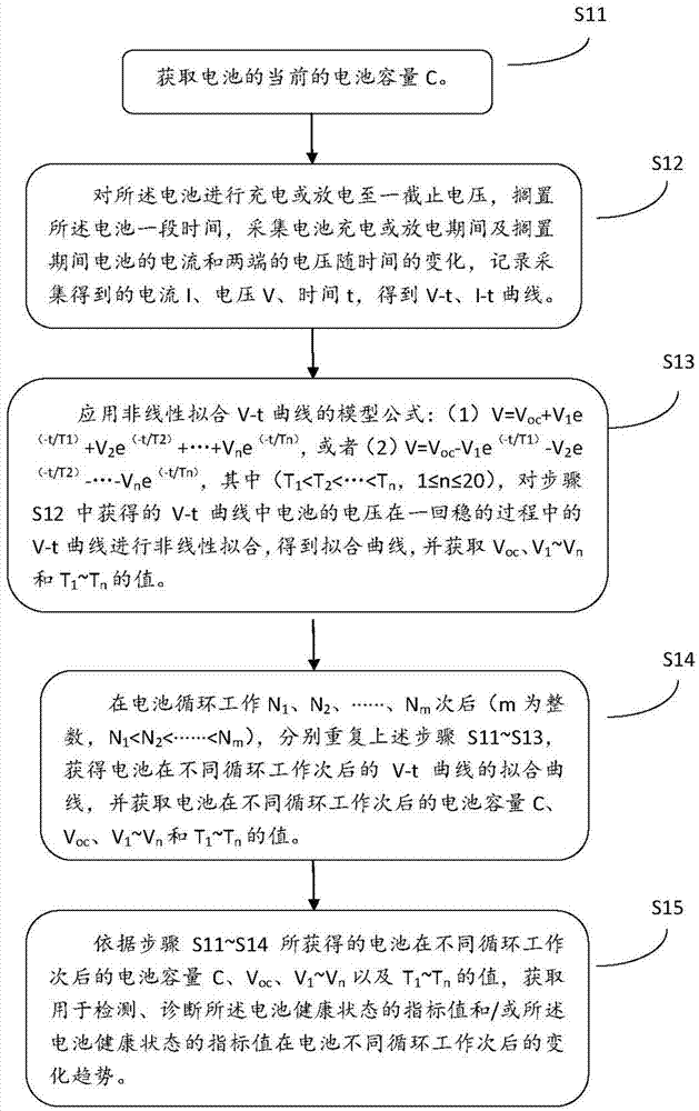
The invention discloses a detection method of a battery health state. The method comprises the following steps: acquiring battery capacity C; charging or discharging a battery to cut-off voltage, idling, acquiring change of current and voltage of the battery during charge or discharge and during the idling to obtain V-t and I-t curves; performing nonlinear fitting on the V-t curve in a voltage stabilizing process in the obtained V-t curve by applying a model formula to obtain a fitting curve and acquiring a reference value; repeating the steps after the battery works for N1, N2, ..., Nm times circularly to obtain fitting curves and reference values of the V-t curves at different life stages of the battery; acquiring an index value for detecting the battery health state and a change tread of the index value after different cycles according to the reference value of the battery after different cycles. In addition, the invention also provides a diagnosis method for the battery health state and a diagnosis method for the battery charge and the health state.

Description

technical field [0001] The invention relates to a method for detecting and diagnosing battery charging capacity and battery health status. Background technique [0002] In recent years, lithium-ion batteries have been widely used in electronic products, new energy vehicles and other fields. However, long-term use of the battery will inevitably cause aging and failure, which will affect the use of the product to a certain extent. [0003] As a stable electrochemical system, the lithium-ion battery has a cycle life of 1000-3000 times and a service life of 5-8 years. The battery's state of charge (SOC, State of Charge, also known as charge capacity) is an indicator used to describe the power contained in the battery. As the battery ages, the battery's capacity gradually decreases. However, electric vehicles require the service life of the power supply to be more than 10 years, which requires us to be able to monitor the decline of the battery during use, and to deeply underst...

Claims


Application Information

Patent Timeline
IPC IPC(8): G01R31/36
Inventor 李宝华钱坤贺艳兵郑勇李懿洋杜鸿达康飞宇
Owner SHENZHEN GRADUATE SCHOOL TSINGHUA UNIV
Learn More