
Test device for 6-DOF gait simulation

A test device and a technology of degrees of freedom, applied in the field of motion simulation, can solve problems such as the large size of the Stewart platform structure, incomplete control of the 6 degrees of freedom of the tibia, and inconsistent active and passive relationships, etc., to achieve a compact and small structure The effect of size and accuracy improvement

Inactive Publication Date: 2016-08-31
SHANGHAI JIAOTONG UNIV
View PDF11 Cites 0 Cited by
  • Summary
  • Abstract
  • Description
  • Claims
  • Application Information

AI Technical Summary

Problems solved by technology

[0003] Through the retrieval of the prior art, it is found that although the previous ankle gait simulator can simulate the main movement of the ankle to a certain extent, and realize the loading of the ankle and the measurement of the vertical ground reaction force, it has the following defects: The 6 degrees of freedom should not be completely controlled, and a simulation of a complete gait support phase cannot be realized; the practice of manipulating the floor for relative movement in some simulators is not conducive to using conventional laboratory equipment, such as force plates and pressure distribution tests Tablet, etc., for data collection and measurement, this method actually does not match the active and passive relationship of real gait movement, and cannot form a dynamic dual relationship
However, the core actuator of this gait simulation device is the UPU Stewart platform fixed on the frame. Although it can realize the movement of six degrees of freedom of the ankle during the gait simulation process, in order to meet the specific test process, the foot To ensure the required displacement of the ankle forward and backward translation, while ensuring that the gait simulation device has good stiffness, and there is no interference between the motion branch chains, the structure size of the Stewart platform is bound to be very large, which will also reduce the accuracy of the simulation device to a certain extent

Method used


Image

  • Test device for 6-DOF gait simulation
  • Test device for 6-DOF gait simulation
  • Test device for 6-DOF gait simulation

Examples


Embodiment 1

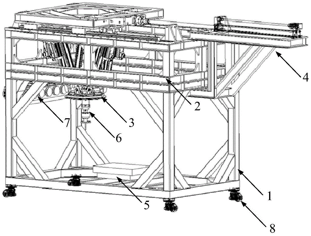
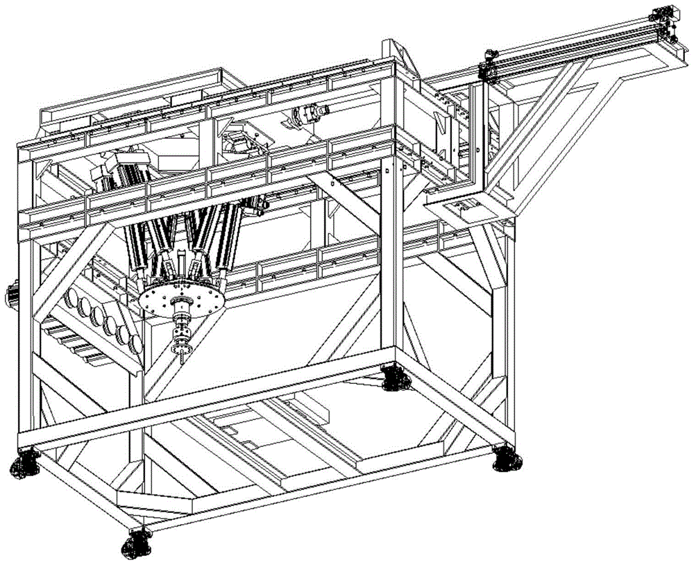
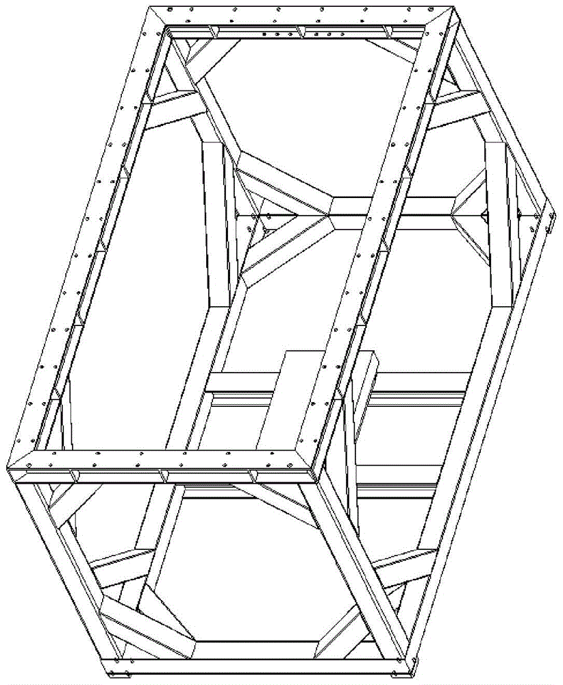
[0027] Such as figure 1 and figure 2 As shown, this embodiment includes: lower frame 1, upper frame 2, parallel mechanism 3, base driving part 4, force measuring plate 5, ankle loading part 6 for clamping tibia, tendon stretching part 7 and horizontal adjustable Adjustable casters 8, wherein: the bottom of the upper frame 2 is connected to the top of the lower frame 1, the horizontally adjustable casters 8 are installed on the bottom of the lower frame 1, the base driving part 4 and the force measuring plate 5 are respectively arranged on the upper frame 2 and the bottom of the lower frame 1, the top of the parallel mechanism 3 is connected with the base driving part 4, and the bottom is connected with the ankle-holding tibial loading part 6, and the ankle-holding tibial loading part 6 is set on the force measuring plate 5 Above, the side of the lower frame 1 is provided with a tendon stretching part 7, and the base driving part 4 and the parallel mechanism 3 respectively co...


PUM


Abstract

A six-degree-of-freedom gait simulation testing device belongs to the technical field of motion simulation. The bottom of an upper frame is connected with the top of a lower frame; a base driving part and a force plate are arranged at the top of the upper frame and the bottom of the lower frame respectively; the top of a parallel mechanism is connected with the base driving part; the bottom of the parallel mechanism is connected with an ankle clamping and tibia loading part; the ankle clamping and tibia loading part is arranged above the force plate; a muscle tendon stretching part is arranged on one side edge of the lower frame; the base driving part and the parallel mechanism are matched with the ankle clamping and tibia loading part respectively. While ensuring the six-degree-of-freedom motion of an ankle relative to the ground, the six-degree-of-freedom gait simulation testing device is reduced in structure size and improved in structural stiffness, shortens the gait simulation period and improves the testing precision.

Description

technical field [0001] The invention relates to a device in the technical field of motion simulation, in particular to a six-degree-of-freedom gait simulation test device based on a movable base Stewart parallel mechanism. Background technique [0002] The foot-ankle complex participates in human movement and is the final weight-bearing part of the human body. The study of its biomechanics has important significance and functions in the fields of foot-ankle disease mechanism, artificial prosthesis, orthopedics, and shoe development. The human biped can be regarded as a complex multi-rigid body mechanical system with multiple degrees of freedom and different rigidities in each direction. The research on the biomechanical characteristics of the ankle gait mainly relies on the ankle gait simulation device. Using this A device that drives the physical ankle system and ankle dynamics model to simulate various sports and mechanical states of the human ankle, such as gait, running,...

Claims


Application Information

Patent Timeline
Patent Type & Authority Patents(China)
IPC IPC(8): G09B25/02
CPCG09B25/02
Inventor 施光林郭秦阳王冬梅
Owner SHANGHAI JIAOTONG UNIV
Learn More