Housing structure of socket electric connector

A technology of electrical connector and shell structure, which is applied in the direction of connection, installation of connection parts, parts of connection devices, etc., can solve problems such as radio frequency interference, electromagnetic wave leakage, electromagnetic interference, etc., to slow down electromagnetic interference and radio frequency interference, reduce The effect of grounding resistance and strengthening holding force

Inactive Publication Date: 2015-04-08
连展科技电子(昆山)有限公司
View PDF0 Cites 7 Cited by
  • Summary
  • Abstract
  • Description
  • Claims
  • Application Information

AI Technical Summary

Problems solved by technology

However, generally the back cover A11 of the shielding shell A1 is not provided with pins, that is to say, there is no pin on the bottom surface A12 of the back cover A11 for soldering the circuit board.
here, figure 2 It is a schematic diagram of EMI simulation analysis after connecting the socket electrical connector and the plug electrical connector in the prior art. It can be clearly seen that the length of the rear cover A11 of the shielding shell A1 is relatively short, that is, the existing rear cover A11 The gap distance between the bottom surface A12 and the terminal pin or the circuit board is greater than 1.0mm. From the distribution of the electromagnetic wave leakage test, it can be seen that the electromagnetic wave leaks from the gap distance to a large extent, causing the electrical socket connector to generate electromagnetic interference when transmitting signals. , Noise problem of radio frequency interference
Moreover, no pins are added to the rear cover A11, so that the holding force between the socket electrical connector and the circuit board is relatively insufficient

Method used


Image

  • Housing structure of socket electric connector
  • Housing structure of socket electric connector
  • Housing structure of socket electric connector

Examples


Embodiment Construction

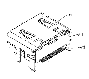
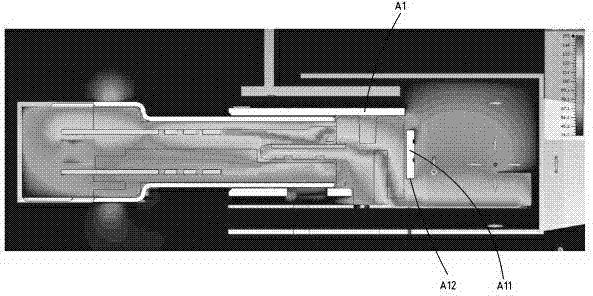
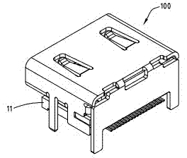
[0041] refer to image 3 , Figure 4 and Figure 5 , is an embodiment of the socket electrical connector 100 of the present invention, image 3 is a schematic diagram of the appearance, Figure 4 For the decomposition diagram, Figure 5 Schematic diagram for EMI analysis. Here, the socket electrical connector 100 is an HDMI connection interface standard, but not limited thereto. In some embodiments, the electrical receptacle connector 100 can be a micro-USB (Type-C) connection interface specification (such as Image 6 shown). In this embodiment, the socket electrical connector 100 includes an insulating body 11 , a plurality of terminals 21 and a shielding shell 31 .

[0042] refer to Figure 4 and Figure 5 , the insulating body 11 is a flat and long board, and the insulating body 11 includes a base 111 and a tongue. The plurality of terminals 21 are located on the insulating body 11 , and the plurality of terminals 21 include a plurality of welding feet 211 exposed...


PUM


Abstract

A housing structure of a socket electric connector includes an insulation body, a plurality of terminals and a shielding shell. The insulation body includes a base. The terminals are disposed on the insulation body. The terminals include a plurality of welding pins exposed outside the bottom of the base. The shielding housing covers the insulation body and includes a top cover board, a rear cover board and a plurality of connecting pins. The top cover board is disposed on the top face of the base. The rear cover board is connected to the rear side of the top cover board. The rear cover board extends downward to the rear side of the base. The rear cover body includes a bottom face. The connecting pins are connected to the bottom face. The shielding shell is disposed on the circuit board. The distance between vertical sections of the bottom face and the circuit board is smaller than or equal to 1.0 mm.

Description

technical field [0001] The invention relates to an electrical connector, in particular to a shell structure of a socket electrical connector. Background technique [0002] Nowadays, all kinds of electronic products are becoming more and more multifunctional, providing infinite convenience and high convenience, but forming a complex electromagnetic wave interference environment, affecting the operation and transmission of electronic products, such as electromagnetic interference (Electromagnetic Interference, EMI), radio frequency interference (Radio Frequency Interference, RFI for short). [0003] The transmission interface specifications of general electrical connectors are quite diverse, such as HDMI or Universal Serial Bus (USB for short), and USB is gradually used by the public, and has been developed with the USB2.0 transmission specification to today's faster transmission speed The USB3.0 transmission specification. [0004] Please refer to figure 1 and figure 2 ,...

Claims


Application Information

Patent Timeline
Patent Type & Authority Applications(China)
IPC IPC(8): H01R13/516H01R13/658
CPCH01R12/71H01R13/516H01R13/6581H01R13/73
Inventor 高雅芬蔡侑伦侯斌元王文郁蔡文贤陈茂胜
Owner 连展科技电子(昆山)有限公司
Why Eureka
Try Eureka