
Micro-grid droop control optimizing method based on sliding-mode control

A technology of optimization method and control method, applied in the direction of AC network circuit, sustainable manufacturing/processing, single network parallel feeding arrangement, etc.

Active Publication Date: 2015-04-08
SHANGHAI UNIVERSITY OF ELECTRIC POWER
View PDF4 Cites 8 Cited by
  • Summary
  • Abstract
  • Description
  • Claims
  • Application Information

AI Technical Summary

Problems solved by technology

[0004] The purpose of the present invention is to provide a micro-grid droop control optimization method based on sliding mode control in order to overcome the defects of the above-mentioned prior art, and the stability margin is low when the droop control is used for the micro-grid composed of distributed power sources through inverters and the problem of insufficient power distribution accuracy, it is proposed to meet the power sharing accuracy by cascading the phase angle and frequency droop control loops, and to design a nonlinear controller by using the sliding mode control method to provide a compensation signal for the voltage loop. Increased system robustness, thus ensuring that the system can remain stable under large disturbances

Method used


Image

  • Micro-grid droop control optimizing method based on sliding-mode control
  • Micro-grid droop control optimizing method based on sliding-mode control
  • Micro-grid droop control optimizing method based on sliding-mode control

Examples


Embodiment

[0042] Below, the present invention will be further explained from several aspects such as droop control principle, droop control optimization strategy, nonlinear compensation controller design method, and calculation example verification.

[0043] ⑴ Droop control principle

[0044] Traditional droop control is:

[0045] ω=ω 0 -mP

[0046] E=E 0 -nQ

[0047] Among them, ω is VSC output angular frequency, ω 0 is the angular frequency set value of the droop control, m is the droop coefficient of the angular frequency ratio to active power, E 0 is the given value of droop control voltage, n is the droop coefficient of voltage ratio reactive power.

[0048] Frequency and voltage droop can distribute active and reactive power proportionally according to the capacity of different DGs. In fact, the given values ​​of frequency and voltage are the communication signals required by each DG in the system. The droop coefficient is obtained from the following formula.

[0049] ...


PUM


Abstract

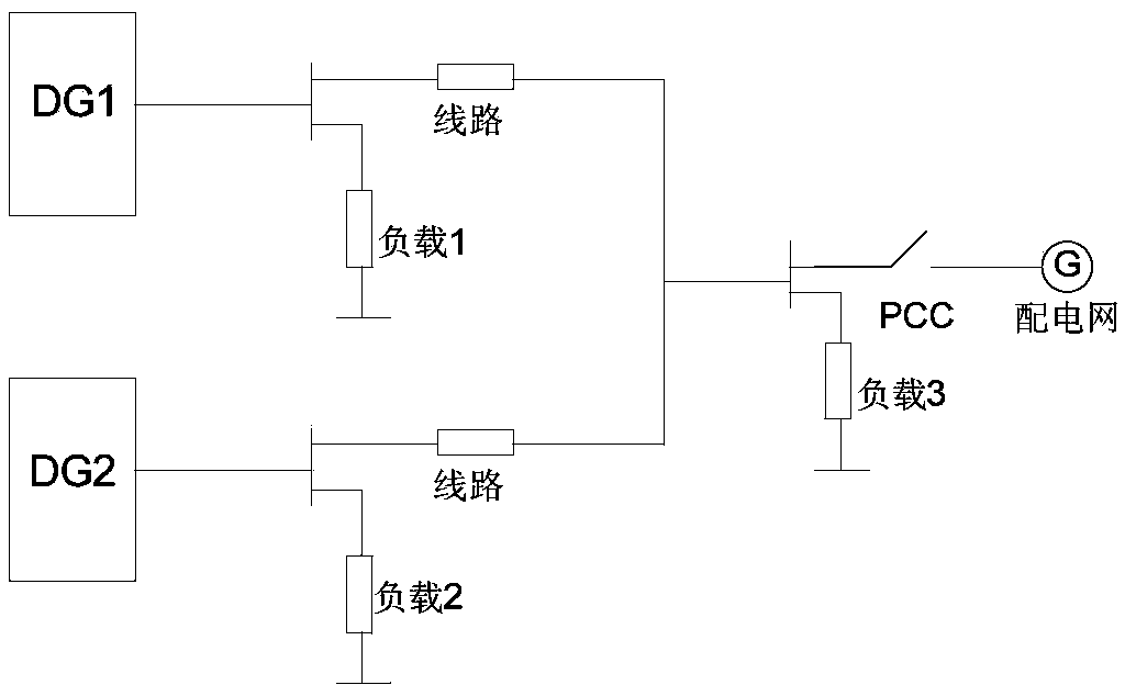
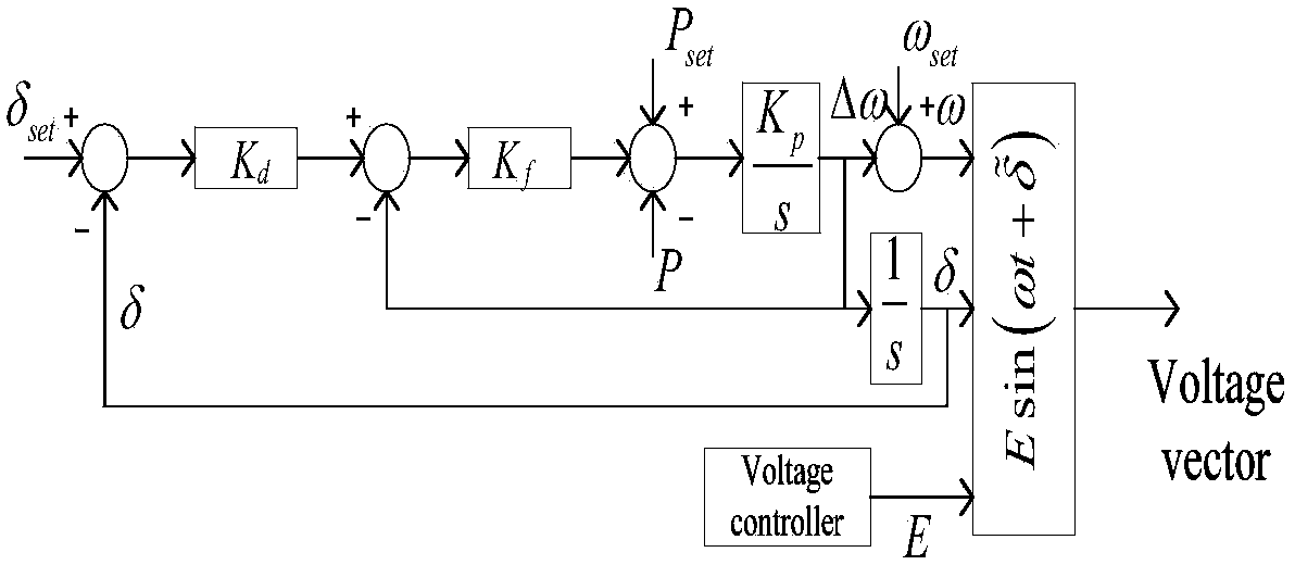
The invention relates to a micro-grid droop control optimizing method based on sliding-mode control. The micro-grid droop control optimizing method based on sliding-mode control comprises the steps of 1) analyzing the structure of two distributed power micro-grids (DG), and computing the internal load current of the micro-grids; 2) enabling each DG to provide active power P and reactive power Q to a bus; 3) performing droop control on phase angles to obtain a dynamic equation; 4) through power-reactive power droop control, designing a voltage magnitude controller; 5) for improving the stability of the droop control, designing a compensating controller; 6) designing the controllers through a sliding-mode control method including firstly, designing a switching function, and secondly, designing sliding-mode control laws. Compared with the prior art, the micro-grid droop control optimizing method based on the sliding-mode control has the advantages of being capable of effectively improving the power distributing precision and the system stability among the distributed power sources of the micro-grids.

Description

technical field [0001] The invention relates to the field of microgrid droop control design, in particular to a microgrid droop control optimization method based on sliding mode control. Background technique [0002] Distributed power sources and energy storage devices (batteries, high-speed flywheels, etc.) can be combined into a micro-grid (referred to as a micro-grid) to provide high-quality uninterrupted power supply to key loads. The microgrid can be used as an independent system to meet the needs of the user side, and can also be connected to the large power grid to improve the reliability of power supply, and has strong flexibility and dispatchability. [0003] In order to meet the uninterrupted demand for power consumption of internal users in the microgrid, the microgrid needs to freely and seamlessly switch between the connected state and the island state. The dual-mode inverter proposed in the prior art adopts PQ current control for networked operation and V-f co...

Claims


Application Information

Patent Timeline
Patent Type & Authority Applications(China)
IPC IPC(8): H02J3/24H02J3/38
CPCY02P80/14H02J3/381H02J3/24
Inventor 符杨米阳李东东夏洪亮
Owner SHANGHAI UNIVERSITY OF ELECTRIC POWER
Learn More