
Micro-grid inverter power control method under complex network topology

A complex network and power control technology, applied in the direction of AC network circuits, single-network parallel feeding arrangements, circuit devices, etc., can solve the problems of reduced system stability and the inability to use complex network topologies, etc.

Pending Publication Date: 2021-05-14
SHANGHAI DIANJI UNIV
View PDF0 Cites 2 Cited by
  • Summary
  • Abstract
  • Description
  • Claims
  • Application Information

AI Technical Summary

Problems solved by technology

[0004] In the existing technologies, the influence of the impedance characteristics in the network on the droop control strategy is ignored. In the actual microgrid, the switching of the inverter and the load will cause the resistance and inductance characteristics of the line impedance corresponding to each inverter unit. Changes occur, and the line impedance may present the following conditions: resistive, inductive, and resistive. Therefore, the conventional virtual impedance method is no longer applicable to complex network topologies (virtual impedance is used to improve the resistive and inductive characteristics of line impedance), At this time, the application of traditional droop control will reduce the stability of the system due to the power coupling of the system, so it cannot be used in complex network topologies

Method used

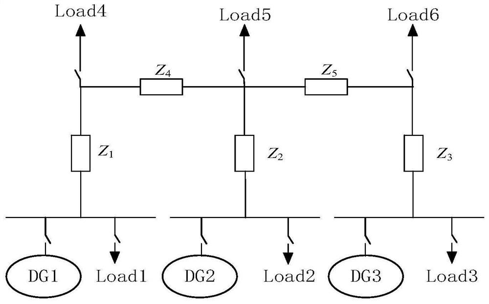
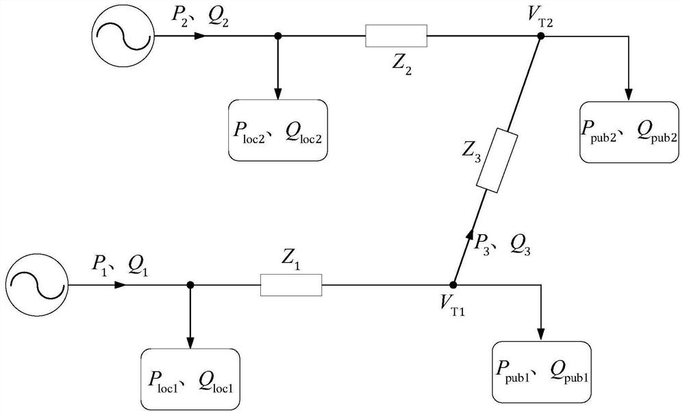
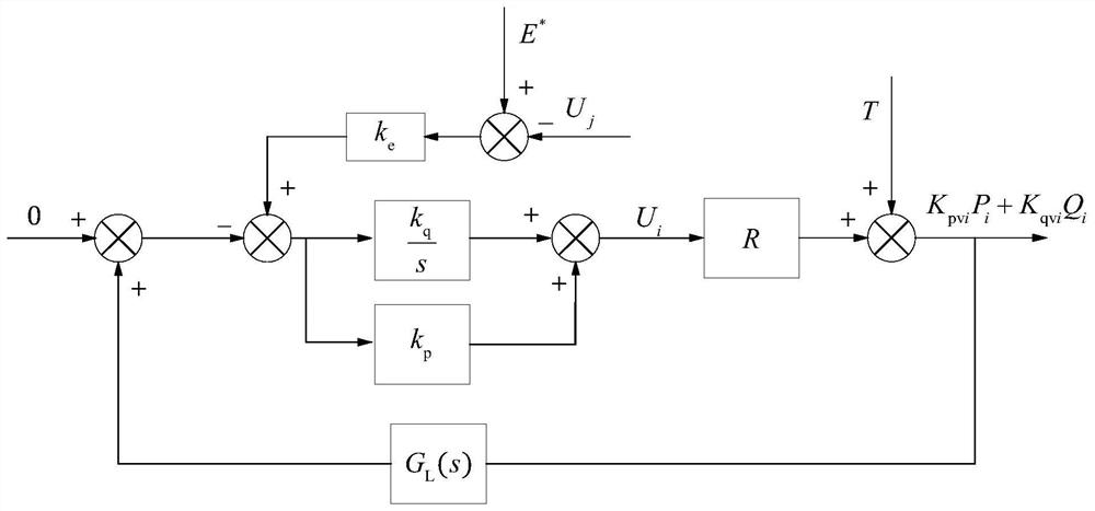

Image

  • Micro-grid inverter power control method under complex network topology
  • Micro-grid inverter power control method under complex network topology
  • Micro-grid inverter power control method under complex network topology

Examples


Embodiment Construction

[0075] The following will clearly and completely describe the technical solutions in the embodiments of the present invention with reference to the drawings in the embodiments of the present invention. Obviously, the described embodiments are part of the embodiments of the present invention, not all of them. Based on the embodiments of the present invention, all other embodiments obtained by persons of ordinary skill in the art without making creative efforts shall fall within the protection scope of the present invention.

[0076] Accordingly, the following detailed description of the embodiments of the invention provided in the accompanying drawings is not intended to limit the scope of the claimed invention, but merely represents selected embodiments of the invention. Based on the embodiments of the present invention, all other embodiments obtained by persons of ordinary skill in the art without creative efforts fall within the protection scope of the present invention.

[...


PUM


Abstract

The invention relates to a micro-grid inverter power control method under a complex network topology. The method comprises the following steps: 1, carrying out power distribution error analysis based on coupling droop control for the complex network topology, so as to determine whether the resistance-inductance type droop control needs to be improved or not; 2, when it is determined that improvement is needed, setting a complex network topology improvement control strategy; and 3, controlling the power of the micro-grid inverter based on the complex network topology improved control strategy. Aiming the problem that the traditional droop control cannot be used and the power distribution of the load is also caused by the change of the line impedance corresponding to the inverter unit due to the switching of the load and the inverter unit in the actual micro-grid system, improved coupling droop control is adopted, it is verified through theory and simulation that the method can be applied to a complex network topology, and the power distribution effect is good.

Description

technical field [0001] The invention relates to the technical field of microgrid inverter unit control, in particular to a power control method for a microgrid inverter under complex network topology. Background technique [0002] The mainstream of micro-grid inverter control adopts droop control technology without communication, which mainly imitates the operating characteristics of synchronous generators in the large power system, and adjusts the output active power of the inverter through the system frequency under the premise that the line impedance is inductive. 1. Adjust the output reactive power of the inverter through the output voltage of the inverter. For droop control under inductive conditions, since the system frequency is a global variable, the active power output by each inverter can be allocated reasonably, and the inverter The output voltage of each inverter is a local variable, that is, the output voltage of each inverter is different due to the difference ...

Claims


Application Information

Patent Timeline
Patent Type & Authority Applications(China)
IPC IPC(8): H02J3/48H02J3/50
CPCH02J3/48H02J3/50H02J2203/20
Inventor 王光楠文传博
Owner SHANGHAI DIANJI UNIV
Learn More