Asynchronous motor

A technology of asynchronous motor and motor shaft, which is applied in the manufacture of motor generators, electrical components, electromechanical devices, etc., can solve the problems that traditional motors cannot meet, difficult to operate, and high manufacturing costs

Active Publication Date: 2015-04-08
南京鑫业电动工具制造有限公司
View PDF7 Cites 9 Cited by
  • Summary
  • Abstract
  • Description
  • Claims
  • Application Information

AI Technical Summary

Problems solved by technology

However, the product structure and circuit of the servo motor are complex, and the manufacturing cost is high; due to the limitation of high-power current, the power of the servo motor is relatively small; before using the servo motor, it is necessary to solve the heat dissipation, magnetic isolation, self-locking and movement of the motor There are many problems such as lightweight components, so the use, operation and maintenance are more complicated; servo motors are mainly used for high-precision industrial equipment (such as CNC, robots), and are not suitable for general-precision power equipment (such as product lines, ordinary Industrial equipment), the largest market demand is often industrial equipment with general precision; servo motors are limited in promotion and application due to high product prices, difficult operation, and small applicable areas
[0006] With the development of industry, the use environment of motors has also undergone great changes. The market puts forward higher requirements for the use of motors. The manual production process is gradually replaced by automated processes. Traditional motors can no longer meet the development of modern industry. The market needs a large number of new motors with advanced functions, technological innovation, economical and practical, wide-ranging, energy-saving and reliable

Method used


Image

  • Asynchronous motor
  • Asynchronous motor
  • Asynchronous motor

Examples


Embodiment Construction

[0028] The present invention will be further described below in conjunction with accompanying drawing, and the structure and principle of this device are very clear to those skilled in the art. It should be understood that the specific embodiments described here are only used to explain the present invention, not to limit the present invention.

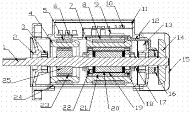
[0029] The invention consists of a motor shaft, a front end cover, a main bearing, a control coil, an auxiliary stator, a strong current terminal, a power coil, a main stator, a driving circuit board, an integrated control board, a wiring control box, a frequency shielding cable, a rear end cover, and a fan. , Rear wind cover, grating encoder, rotor bearing, rotor end cover, phase change magnetic material, main inner rotor, main outer rotor, skeleton oil seal, permanent magnet strip, motor casing, auxiliary rotor and other corresponding spare parts to form the whole machine product.

[0030] The invention includes a stator and a roto...


PUM


Abstract

The invention relates to the field of general and wide power control application, in particular to an asynchronous motor, comprising stators and rotors; in the asynchronous motor, two groups of rotor-stator structures are installed coaxially; one group is a power rotor-stator structure which is composed of main stators and main rotors; the main rotors are formed by embedding a main internal rotor into a main external rotor; a cavity is formed between the main internal rotor and the main external rotor; a phase-change magnetic material is arranged in the cavity; the main internal rotor is connected with the output shaft of the motor; the other group is a control stator-rotor structure which is composed of secondary stators and secondary rotors; the secondary rotors and the main internal rotor are installed coaxially. The outside adopts a standard motor holder structure with a huge wiring control box and the real-time control for the motor is realized; the inside adopts the two groups of the rotor-stator structures; a flowing phase-change magnetic material is filled between the internal rotor and the external rotor, so that the motor automatically has the technical features of current limitation, flexible transmission (starting), controlling of temperature rising, overloading protection, high efficiency and energy conservation and the like.

Description

[technical field] [0001] The invention relates to a wide range of power control applications, specifically an integrated AC asynchronous motor combined with flexible transmission materials, double-rotating stator structure, speed-regulating braking technology, closed-loop servo control and standard product technology, especially suitable for It is suitable for occasions where the motor starts frequently, the load variable is large, and single-machine automatic or integrated system control is required. [Background technique] [0002] The existing motor products are basically divided into two categories according to the technical level, one is the traditional AC and DC motors, which have a long history and a wide variety of products, and basically use traditional electrical control methods to implement applications; the other is more advanced Stepper motors and servo motors are mainly used in high-precision technical fields, such as CNC machine tools, machining center equipmen...

Claims


Application Information

Patent Timeline
Patent Type & Authority Applications(China)
IPC IPC(8): H02K16/00H02K5/22H02K11/00H02K15/00H02K11/22H02K11/30
CPCH02K5/225H02K15/00H02K16/00
Inventor 不公告发明人
Owner 南京鑫业电动工具制造有限公司
Why Eureka
Try Eureka