Turbine assembly drill jig

A technology of turbine components and drilling jigs, which is applied in the direction of clamping, manufacturing tools, metal processing machinery parts, etc., can solve the problems of low processing efficiency and difficulty in guaranteeing the drilling accuracy of turbine hubs, etc., so as to improve production efficiency, avoid errors, and not The effect of lower pass rate

Inactive Publication Date: 2015-04-15
LIUZHOU GUOSHUN MECHANICAL MFR +1
View PDF7 Cites 8 Cited by
  • Summary
  • Abstract
  • Description
  • Claims
  • Application Information

AI Technical Summary

Problems solved by technology

[0003] The problem to be solved by the present invention is to provide a drilling jig for turbine components to solve the problems that the drilling accuracy of the existing turbine hub is difficult to guarantee and the processing efficiency is low

Method used


Image

  • Turbine assembly drill jig

Examples


Embodiment Construction

[0009] Embodiments of the present invention are described in further detail below in conjunction with the accompanying drawings:

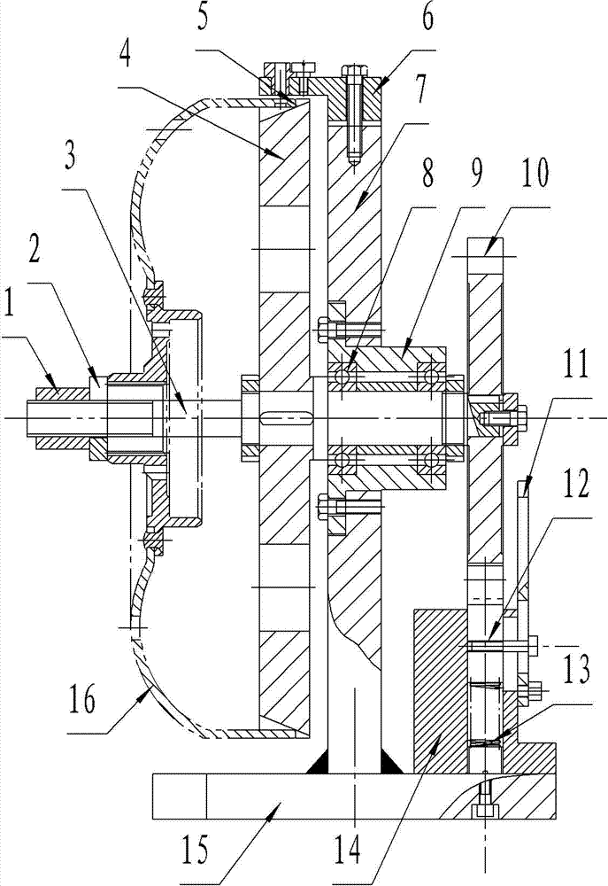
[0010] like figure 1 The shown turbine assembly drilling jig includes a support 7 vertically installed on the base 15, a rotating shaft 3 passes through the middle part of the support 7 horizontally through the bearing 8 and the bearing seat 9, and a Axle sleeve, rotating shaft 3 is equipped with a circular plate 4 for positioning the end face of the turbine hub 16 at the front part of the support 7, and the periphery of the circular plate 7 is provided with a groove 5 for positioning the end face of the turbine hub 16, and the support 7 The upper end is equipped with a curved plate 6 bent forward, the end surface of the turbine hub 16 is placed in the groove 5 of the circular plate 7, and is limited by the curved plate 6, the front end of the rotating shaft 3 passes through the shaft hole of the turbine hub 16 and passes through the nut 1 Fastene...


PUM


Abstract

The invention discloses a turbine assembly drill jig. The turbine assembly drill jig comprises a support base vertically mounted on a base, a rotating shaft horizontally penetrates the middle portion of the support base through a bearing and a bearing seat, a round plate for positioning the end surface of a turbine hub is mounted on the front portion of the support base on the rotating shaft, a grading plate for rotating the round plate for grading the turbine hub is mounted on the rear portion of the support base on the rotating shaft, a bending plate bent forwards is mounted at the upper end of the support base, and grooves for positioning the end surface of the turbine hub is arranged on the periphery of the round plate. Compared with the prior art, the turbine assembly drill jig can solve the problems that the accuracy of existing turbine hub drilling is difficult to ensure and the machining efficiency is low.

Description

technical field [0001] The invention relates to the technical field of machining, in particular to a drilling jig for machining multiple holes on a turbine hub assembly. Background technique [0002] The turbine hub assembly has a disc-shaped shell with a concave center and a protruding periphery. There are multiple holes in the protruding part of the periphery. The center of the shell is provided with a shaft hole perpendicular to the shell. The process requirements are relatively high. After assembly, the shaft must be able to Rotate easily by hand, while ensuring that the deflection between the positioning end face of the positioning plate and the outer circle cannot exceed 0.05mm, and the circumferential indexing error of the outer circle cannot exceed 0.08mm. Existing enterprises generally use a fitter to mark the multiple holes on the turbine hub assembly first, and then place the turbine hub assembly squarely on the workbench of the drilling machine, so that the posit...

Claims


Application Information

Patent Timeline
Patent Type & Authority Applications(China)
IPC IPC(8): B23Q3/06B23Q16/02
CPCB23Q3/062B23Q16/025B23Q16/027
Inventor 陈国财
Owner LIUZHOU GUOSHUN MECHANICAL MFR
Why Eureka
Try Eureka