Electric automatic control system of boiler dust removal pneumatic transmission system

A technology of electrical automatic control and pneumatic conveying system, applied in conveyors, conveying bulk materials, transportation and packaging, etc., can solve the problems of large flow rate of roots blower, large motor power, large energy consumption, etc., to reduce air volume and liters. The effect of reducing pressure and comprehensive energy consumption

Active Publication Date: 2015-04-15
桐乡市腾飞家纺股份有限公司
View PDF5 Cites 5 Cited by
  • Summary
  • Abstract
  • Description
  • Claims
  • Application Information

AI Technical Summary

Problems solved by technology

[0002] Traditional pneumatic conveying for boiler ash removal mostly adopts large-flow Roots blower dilute-phase low-speed conveying, which requires a large flow of Roots blower, large motor power, large energy consumption, and high operating costs

Method used


Image

  • Electric automatic control system of boiler dust removal pneumatic transmission system

Examples


Embodiment 1

[0009] Example 1 Composition and functions of an electrical automatic control system for a boiler ash removal pneumatic conveying system:

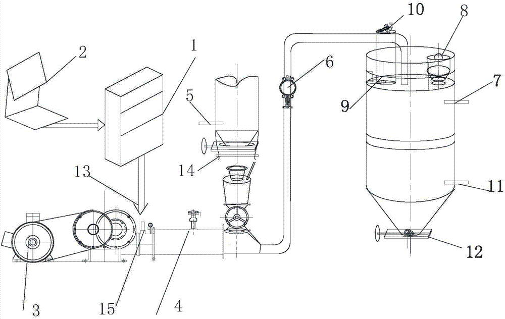
[0010] The invention relates to an electric automatic control system of a boiler ash removal pneumatic conveying system. The electric automatic control system includes a PLC programmable control system 1, an industrial control computer or a DCS system 2, a Roots blower motor 3, a pressure transmitter 4, and a low-level material Level gauge 5, pneumatic switch valve 6, high level material level gauge 7, pressure release valve 8, pulse back blowing bag type silo dust collector pulse valve 9, pulse back blowing bag type silo dust collector induced fan motor 10, low level material Position meter 11, pneumatic plug-in valve 12, signal transmission cable 13, load cell 14, mass flow meter 15, is characterized in that the electrical automatic control system is centralized controlled by PLC programmable control system 1, and its material-gas ratio...

Embodiment 2

[0011] Example 2 The working process of an electrical automatic control system for a boiler ash removal pneumatic conveying system:

[0012] The industrial computer or DCS system 2 uses the PLC programmable control system 1 to measure the data through the load cell 14 and the mass flow meter 15 according to the material-gas ratio, and convert the pressure from the Roots blower according to the ratio of the material-gas ratio of 28-30. The airflow with the set pressure value of the conveyor 4 and the material added by the material hopper are accelerated in the gas-solid mixing acceleration chamber and transported to the material pipeline. According to the process and production needs, the pneumatic switch valve 6 distributes it into the warehouse, and the high-level material level gauge 7 And the low-level material level gauge 11 is installed on the silo for controlling the material level of the silo. When the pressure value in the silo pump and the silo exceeds the set value...


PUM


Abstract

The invention relates to an electric automatic control system of a boiler dust removal pneumatic transmission system. The electric automatic control system comprises a PLC (programmable logic control) system 1, an IPC (industrial personal computer) DCS (distributed control system) e, a Roots blower motor 3, a pressure transmitter 4, a low level gauge 5, a pneumatic reversing valve 6, a high level gauge 7, a pressure release valve 8, a pulse jet pocket type bin dust cleaner pulse valve 9, a pulse jet pocket type bin dust cleaner draft fan motor 10, a low level gauge 11, a pneumatic gate valve 12, a signal transmission cable 13, a weighing sensor 14 and a mass flowmeter 15. The electric automatic control system of the boiler dust removal pneumatic transmission system is characterized by being integrally controlled by the PLC system 1 and performing adjustment on pipeline equipment according to a material-to-gas ratio of 28-30. The electric automatic control system of the boiler dust removal pneumatic transmission system has the advantages of achieving action linkage of relevant parts during a control process to perform actions automatically, ensuring optimized control of the material-to-gas ratio during a transmission process, reducing the air volume and the pressure boost of a Roots blower and further greatly reducing comprehensive energy consumption.

Description

technical field [0001] The present invention relates to an electrical automatic control system of a boiler ash removal pneumatic conveying system, in particular to a boiler that can transport powder materials such as boiler ash with a small bulk density and a large bulk ratio, which can be transported over a long distance and can be transported from one point to multiple points. The invention relates to an electric automatic control system of an ash removal pneumatic conveying system, which belongs to the technical field of electric automatic control of pneumatic conveying. Background technique [0002] Traditional pneumatic conveying for boiler ash removal mostly adopts large-flow Roots blower dilute-phase low-speed conveying, which requires a large flow of Roots blower, large motor power, large energy consumption, and high operating costs. The invention is an electrical automatic control system matching a boiler ash removal pneumatic conveying system. Contents of the inv...

Claims


Application Information

Patent Timeline
Patent Type & Authority Applications(China)
IPC IPC(8): B65G53/66
Inventor 郭志年
Owner 桐乡市腾飞家纺股份有限公司
Why Eureka
Try Eureka