Automatic electrical control system of pneumatic wheat conveying system

A technology of electric automatic control and pneumatic conveying system, which is applied to conveyors, conveying bulk materials, transportation and packaging, etc. It can solve the problems of blocked pipelines and easy formation of embolism, and achieves the goals of saving compressed air, reducing operating costs and optimizing control Effect

Inactive Publication Date: 2015-04-29
NINGXIA JIAXIANG AUTOMATIC CONTROL TECH
View PDF7 Cites 7 Cited by
  • Summary
  • Abstract
  • Description
  • Claims
  • Application Information

AI Technical Summary

Problems solved by technology

[0002] Traditional wheat storage warehouses use fans as the air source during the transportation and storage of warehouses, which can only transport wheat at low pressure and low wind speed, and when the pipe is full, it is easy to form an embolism and block the pipe

Method used


Image

  • Automatic electrical control system of pneumatic wheat conveying system

Examples


Embodiment 1

[0010] The composition and effect of the electric automatic control system of the pneumatic conveying system of a kind of wheat of embodiment 1:

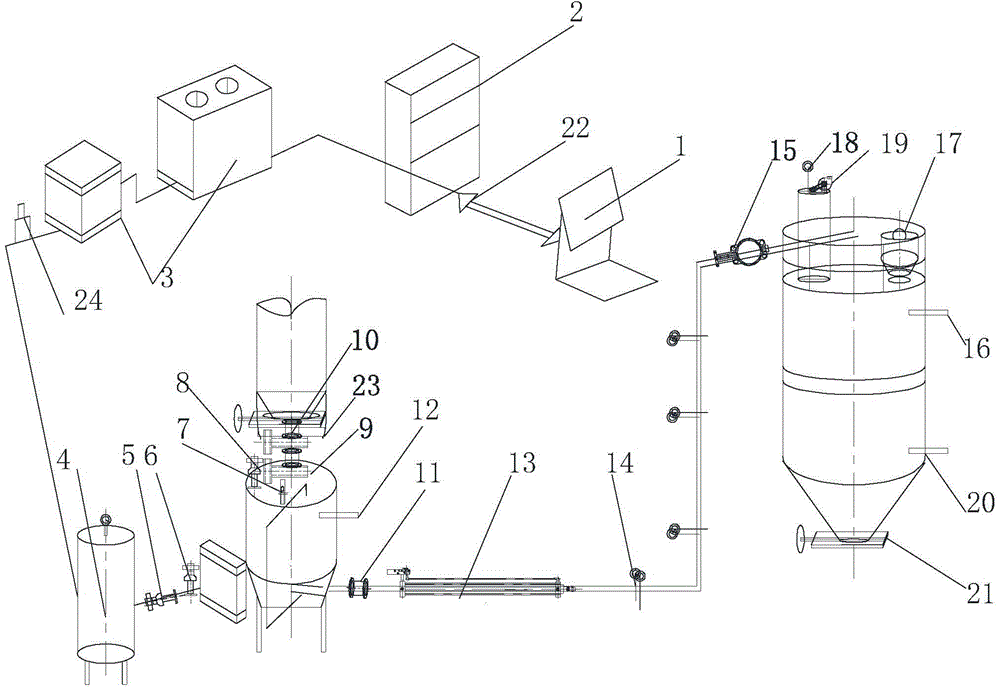
[0011] Electrical automatic control system includes PLC programmable control system 1, industrial computer or DCS system 2, air compressor and freeze dryer motor 3, electric contact pressure gauge 4, pressure regulating valve 5, upper intake valve 6, pneumatic exhaust valve 7. Pressure transmitter 8, pneumatic feed valve 9, pneumatic pre-closing valve 10, pneumatic discharge valve 11, high level gauge 12, gas booster 13, pulse air knife valve 14, pneumatic switch valve 15, High-level material level gauge 16, pressure release valve 17, pulse valve for bag-type silo dust collector 18, pulse-back blow bag-type silo dust collector induced fan motor 19, low-level material level gauge 20, pneumatic flapper valve 21, Signal transmission cable 22, weighing sensor 23, mass flow meter 24, is characterized in that the electrical automatic cont...

Embodiment 2

[0012] The working process of the electric automatic control system of the pneumatic conveying system of a kind of embodiment 2 wheat:

[0013] The industrial computer or DCS system 2 uses the PLC programmable control system 1 to measure the data through the load cell 23 and the mass flow meter 24 according to the material-gas ratio, and adjusts the pressure of the gas coming out of the gas storage tank according to the ratio of the material-gas ratio of 20-22. The compressed air with the set pressure value of the valve 5 discharges the material added from the material hopper into the outlet of the warehouse pump through the pneumatic discharge valve 11, and transports it to the material pipeline, and is distributed into the warehouse by the pneumatic switching valve 15 according to the process and production needs. The high-level material level gauge 16 and the low-level material level gauge 20 are installed on the silo for controlling the material level of the silo. When th...


PUM


Abstract

The invention relates to an automatic electrical control system of a pneumatic wheat conveying system. The automatic electrical control system comprise a PLC system 1, an industrial control or DCS 2, an air compressor and freezing and drying motor 3, an electric contact pressure gauge 4, a pressure adjusting valve 5, an upper air feed valve 6, a pneumatic exhaust valve 7, a pressure transducer 8, a pneumatic feed valve 9, a pneumatic pre-closing valve 10, a pneumatic discharge valve 111, a high level material level meter 12, an air pressurizing device 13, a pulse air blade valve 14, a pneumatic change valve 15, a high level material level meter 16, a pressure relief valve 17, a pulse reverse bag blowing type material bin dust remover pulse valve 18, a pulse reverse bag blowing type material bin dust remover air guiding fan motor 19, a low level material level meter 20, a pneumatic gate valve 21, a signal transmission cable 22, a weighing sensor 23 and a mass flow meter 24. The automatic electrical control system is characterized in that the system is controlled by the PLC system 1 in a concentrated manner, the material-air ratio ranges from 20 to 22, and the pipeline equipment is adjusted according to the material-air ratio.

Description

technical field [0001] The invention relates to an electrical automatic control system of a pneumatic conveying system for wheat, which can be transported from one point to multiple points and can be transported over a long distance. . Background technique [0002] Traditional wheat storage warehouses use fans as air sources during the transportation and storage of warehouses, which can only transport wheat at low pressure and low wind speed, and when the pipe is full, it is easy to form an embolism and block the pipe. The invention is matched with a kind of compressed air as the gas source, the compressed air consumes less gas, the power of the matching gas storage tank and the motor is lower, and it will not form embolism when the tube is full, and the operating cost is low. The utility model relates to an electric automatic control system of a wheat pneumatic conveying system. Contents of the invention [0003] The purpose of the present invention is to match with a k...

Claims


Application Information

Patent Timeline
Patent Type & Authority Applications(China)
IPC IPC(8): B65G53/66
Inventor 郭志年
Owner NINGXIA JIAXIANG AUTOMATIC CONTROL TECH
Why Eureka
Try Eureka