
Hydraulic oil tank, hydraulic system with hydraulic oil tank and vehicle

A technology of hydraulic oil tank and hydraulic system, applied in the field of vehicles, can solve problems such as shortening life, component failure, affecting sealing performance, etc., to prevent volumetric efficiency, protect fit tolerance, and prolong service life.

Inactive Publication Date: 2015-04-15
BEIQI FOTON MOTOR CO LTD
View PDF5 Cites 2 Cited by
  • Summary
  • Abstract
  • Description
  • Claims
  • Application Information

AI Technical Summary

Problems solved by technology

[0006] The technical problem to be solved by the present invention is to solve the problem that the hydraulic oil tank in the hydraulic system of the existing self-unloading engineering vehicle can only rely on the temperature difference between itself and the ambient temperature for self-cooling, and the cooling method has a great influence on the frequency of use of the vehicle and the ambient temperature; When the hydraulic oil temperature reduction requirements are not met, the hydraulic oil temperature will rise rapidly. When the oil temperature is too high, the hydraulic oil viscosity, system volumetric efficiency, and hydraulic system work efficiency will all decrease, increasing the hidden danger of leakage; The thermal expansion of the parts affects the normal clearance fit between the parts and causes the failure of the parts, and the rise of the oil temperature will accelerate the aging and deterioration of the rubber parts, shorten the life and affect the sealing performance

Method used


Image

  • Hydraulic oil tank, hydraulic system with hydraulic oil tank and vehicle
  • Hydraulic oil tank, hydraulic system with hydraulic oil tank and vehicle

Examples


Embodiment Construction

[0021] In order to make the purpose, technical solutions and advantages of the embodiments of the present invention clearer, the technical solutions in the embodiments of the present invention will be clearly and completely described below in conjunction with the drawings in the embodiments of the present invention. Obviously, the described embodiments It is a part of embodiments of the present invention, but not all embodiments. Based on the embodiments of the present invention, all other embodiments obtained by persons of ordinary skill in the art without making creative efforts belong to the protection scope of the present invention.

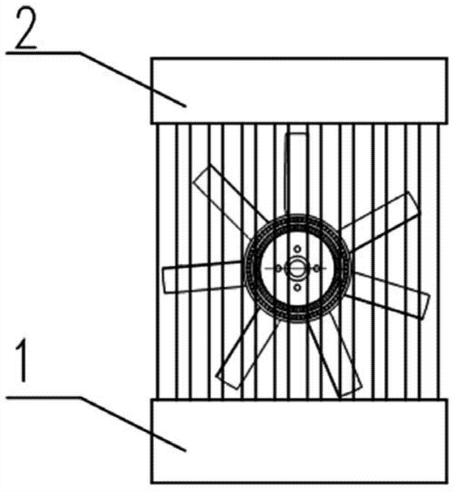
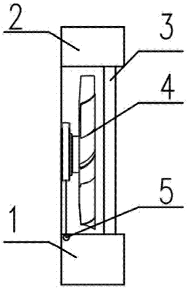
[0022] A hydraulic oil tank provided by the present invention, the hydraulic oil tank includes an oil temperature detection unit and a temperature reduction execution unit, the oil temperature detection unit is used to detect the temperature value of hydraulic oil and feed back the detected temperature value to the temperature reduction execut...


PUM


Abstract

The invention relates to the technical field of vehicles, in particular to a hydraulic oil tank, a hydraulic system with the hydraulic oil tank and a vehicle. The hydraulic oil tank is suitable for a dumping engineering truck and has the heat radiating function and comprises an oil temperature detection unit and a cooling execution unit; the oil temperature detection unit is used for detecting the temperature value of hydraulic oil and feeds back the detected temperature value to the cooling execution unit; and the cooling execution unit is used for receiving the temperature value fed back by the oil temperature detection unit and judges whether cooling work is executed on the oil tank or not according to the temperature vale. According to the hydraulic oil tank, the temperature of the hydraulic oil in a dumping system is effectively controlled, and the phenomenon that due to the fact that the temperature of the hydraulic oil is too high, the volume efficiency and the working efficiency of the hydraulic system are reduced is avoided. The fit tolerance of parts is protected, the service life of sealing parts is prolonged, the failure rate of the parts is effectively reduced, normal work of the parts is ensured, normal work of the hydraulic system is ensured, and the performance of the whole vehicle is improved.

Description

technical field [0001] The invention relates to the technical field of vehicles, in particular to a hydraulic oil tank, a hydraulic system and a vehicle provided with the hydraulic oil tank, in particular to a hydraulic oil tank suitable for dump engineering vehicles and having a heat dissipation function. Background technique [0002] At present, the moving medium of the hydraulic system in the self-unloading engineering vehicles on the market basically uses hydraulic oil, and the engineering vehicles are generally overloaded during use, and the operation of the self-unloading engineering vehicles is relatively complicated, and it is generally non-intermittent operation. Under such working conditions, the long-term and frequent use of the hydraulic system by the engineering vehicle is likely to cause the oil temperature of the hydraulic oil to rise. [0003] During use, the vehicle is in a static state, and the hydraulic oil in the hydraulic oil tank can only self-cool thro...

Claims


Application Information

Patent Timeline
Patent Type & Authority Applications(China)
IPC IPC(8): F15B1/26F15B21/04F15B21/0423
CPCF15B1/26F15B21/045F15B21/0423
Inventor 宋建功凌丽红初超郏孟安
Owner BEIQI FOTON MOTOR CO LTD
Learn More