

Gas storage tank
A technology of gas storage tanks and tanks, which is applied in the direction of gas/liquid distribution and storage, container discharge methods, container filling methods, etc., and can solve the problems affecting the service life of urban pipe networks, hidden dangers of operators, and operating hazards of operators, etc. problems, to achieve the effect of reducing employee work-related injuries, improving safety, and facilitating operation
Inactive Publication Date: 2015-04-15
扬州三方电器有限公司
View PDF0 Cites 1 Cited by
- Summary
- Abstract
- Description
- Claims
- Application Information
AI Technical Summary
Problems solved by technology
[0002] Gas storage tanks are widely used in chemical industry, electronics, metal smelting and other industrial fields. Gas storage tanks are used to store industrial gases, but most of the gases contain a large amount of water vapor, which will gradually condense and form in the storage tanks. Condensed water brings safety hazards to the gas storage tank, and the condensed water must be removed from the gas storage tank. At present, many gas storage tanks discharge the condensed water directly to the ground, which is easy to frostbite the operator and bring harm to the operator. There are potential safety hazards and safety accidents. At present, there will be a lot of condensed water in many gas storage tanks, but the condensed water cannot be discharged well, and the condensed water will often be discharged randomly. This way of discharge often causes ground There will be a lot of condensed water, and it may freeze on the ground in winter, which will bring danger to the operation of the operator. Even if there is a mechanism for storing condensed water, but when the water storage mechanism is full, how to remove the condensed water is also a problem. A problem. Many enterprises directly pour water into the urban pipe network. This will cause too much load on the urban pipe network, cause erosion to the urban pipe network, and affect the service life of the urban pipe network. How to properly remove condensed water has become an industry issues of concern
Method used
View moreImage
Smart ImageViewing Examples

Examples
Embodiment Construction
[0010] The present invention will be further described below in conjunction with the accompanying drawings.
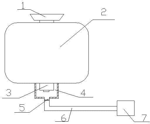
[0011] A gas storage tank, comprising an air inlet 1, a tank body 2, and an air outlet 3, the upper part of the tank body 2 is provided with an air inlet 1, and the gas outlet 3 is located at the lower part of the tank body 2, and the tank body 2 is cylindrical, The bottom of the tank body 2 is provided with a liquid collection tank 4, and a drain pipe 5 is provided below the liquid collection tank 4. The liquid discharge pipe 5 is directly connected to the waste water pipe network 6, and the waste water pipe network 6 is connected to the enterprise waste water treatment pool 7.
Login to View More PUM
 Abstract
The invention discloses a gas storage tank. The gas storage tank comprises a gas inlet, a tank body, and a gas outlet; the upper part of the tank body is provided with the gas inlet; the gas outlet is arranged on the lower part of the tank body; the bottom of the tank body is provided with a liquid collect box; and a liquid exhaust pipe is arranged below the liquid collect box. The gas storage tank is simple in structure, and is convenient for operation; the bottom of the tank body is provided with the liquid collect box, so that collection of condensate water is more convenient, safety of operation staff is increased, operation staff is protected from cold injury, operation reasonable performance is improved, operators are protected from injuries, occupational injury of employees is reduced, and safe production is ensured; waste condensate water is delivered into a waste water pipe network, so that waste condensate water can be delivered into an enterprise waste water processing system directly for waste water treatment, and then is discharged into a city pipe network; pressure of the city pipe network is reduced, the city pipe network is protected, direct corrosion of pipeline caused by discharged waste water is avoided, and service life of the city pipe network is prolonged.
Description
technical field [0001] The invention relates to a gas storage tank. Background technique [0002] Gas storage tanks are widely used in chemical industry, electronics, metal smelting and other industrial fields. Gas storage tanks are used to store industrial gases, but most of the gases contain a large amount of water vapor, which will gradually condense and form in the storage tanks. Condensed water brings safety hazards to the gas storage tank, and the condensed water must be removed from the gas storage tank. At present, many gas storage tanks discharge the condensed water directly to the ground, which is easy to frostbite the operator and bring harm to the operator. There are potential safety hazards and safety accidents. At present, there will be a lot of condensed water in many gas storage tanks, but the condensed water cannot be discharged well, and the condensed water will often be discharged randomly. This way of discharge often causes ground There will be a lot of ...
Claims
Login to View More Application Information
Patent Timeline
 Patent Type & AuthorityApplications(China)
IPC IPC(8): F17C13/10
Inventor纪进
Owner扬州三方电器有限公司