
Lens set mounting component and optical measuring system with same

An optical measurement system and a technology for installing components, applied in the field of multi-optical system confocal measurement or imaging, can solve the problems of high difficulty in completion, high cost, and impact on measurement efficiency, so as to improve measurement efficiency, reduce costs, and improve Effects on system reliability and stability

Active Publication Date: 2015-04-15
RAINTREE SCI INSTR SHANGHAI
View PDF9 Cites 0 Cited by
  • Summary
  • Abstract
  • Description
  • Claims
  • Application Information

AI Technical Summary

Problems solved by technology

[0004] These two methods need to focus continuously because they need to move the wafer under test or each measurement system. On the one hand, the motion platform is required to have high motion reliability, repeat positioning accuracy and service life, so its cost is relatively high; On the one hand, the measurement cycle includes multiple focusing actions and movements, which are difficult to complete in a short period of time, thus affecting measurement efficiency

Method used


Image

  • Lens set mounting component and optical measuring system with same
  • Lens set mounting component and optical measuring system with same
  • Lens set mounting component and optical measuring system with same

Examples


Embodiment Construction

[0064]In the following detailed description of the embodiments, reference is made to the accompanying drawings that form a part hereof. The drawings show, by way of example, specific embodiments in which the invention may be practiced. The illustrated embodiments are not intended to be exhaustive of all embodiments according to the invention. It is to be understood that other embodiments may be utilized and structural or logical changes may be made without departing from the scope of the present invention. With respect to the drawings, directional terms, such as "below," "upper," "left," "right," etc., are used with reference to the orientation of the drawings being described. Since components of embodiments of the invention can be implemented in a variety of orientations, these directional terms are used for purposes of description, not limitation. Accordingly, the following detailed description is not intended to be limiting, and the scope of the invention is defined by th...


PUM


Abstract

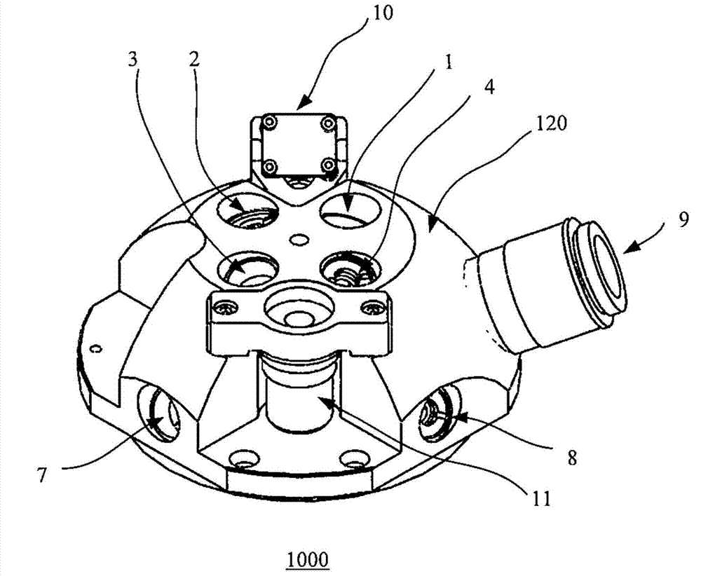
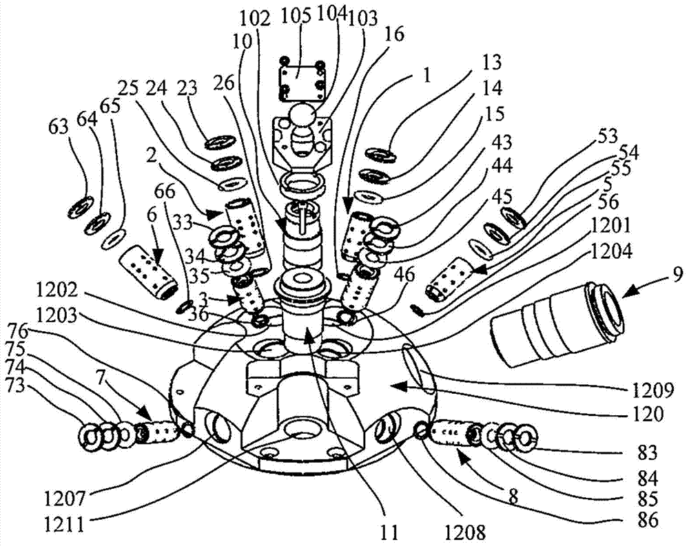
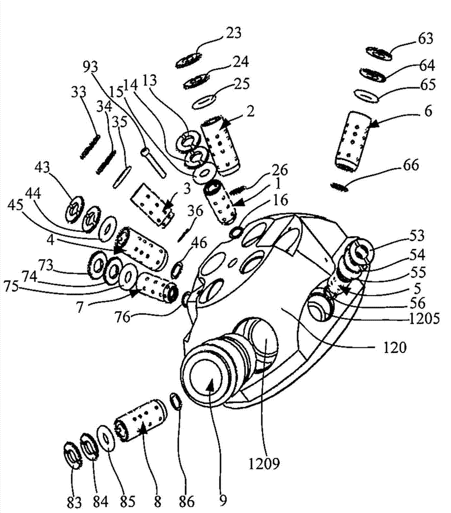
A lens set mounting component comprises a base, a light path positioning lens set, at least two light path detecting lens sets and an observable light path lens set. The light path positioning lens set is mounted on the base and used for positioning a confocal plane of a component to be measured below the bottom of the base, the light path detecting lens sets are mounted on the base and used for detecting different light paths, the observable light path lens set is mounted in the base, and when one of the light path detecting lens sets detects the component to be measured, imaging of the light path detecting lens set is observable by the observable light path lens set, wherein focuses of the light path detecting lens sets and the observable light path lens set are the same and limited on the confocal plane. By the lens set mounting component, frequent actions and repeated positioning of a moving platform are avoided, and system reliability and stability are improved; through multichannel parallel measurement, measuring efficiency is improved and cost is reduced.

Description

technical field [0001] The invention relates to the realization of a multi-optical system confocal measurement or imaging, in particular to the measurement, imaging and processing modules on semiconductor large-scale integrated circuit manufacturing and testing equipment. Background technique [0002] In the manufacturing and testing process of semiconductor large-scale integrated circuits, it is often necessary to use multiple optical systems (that is, multiple independent optical paths) to measure, image or process a certain point on the wafer. The following is an example of measurement equipment: [0003] There are two common methods: one is to keep the measurement point still, move each or each group of measurement systems in turn to focus on the measurement point for measurement, after one or a group of measurement systems have measured, move it away from the measurement point, and then move the One or the next group of measurement systems moves to the measurement point...

Claims


Application Information

Patent Timeline
Patent Type & Authority Applications(China)
IPC IPC(8): G02B7/02G02B7/182
CPCG02B7/021G02B7/04G02B7/182
Inventor 马涛陈星高海军刘军凯
Owner RAINTREE SCI INSTR SHANGHAI
Learn More