Deep ploughing, deep scarification and ridge smashing drill bit
A kind of powder ridge and drill bit technology, which is applied in the fields of farming machinery, application, agricultural machinery and implements, etc. It can solve the problems of high rotation resistance of the powder ridge drill bit, slow speed of plowing land, poor soil crushing effect, etc., and achieves increased crushing effect, walking Increased speed and reduced travel resistance
- Summary
- Abstract
- Description
- Claims
- Application Information
AI Technical Summary
Problems solved by technology
Method used
Image

Examples
specific Embodiment approach 1
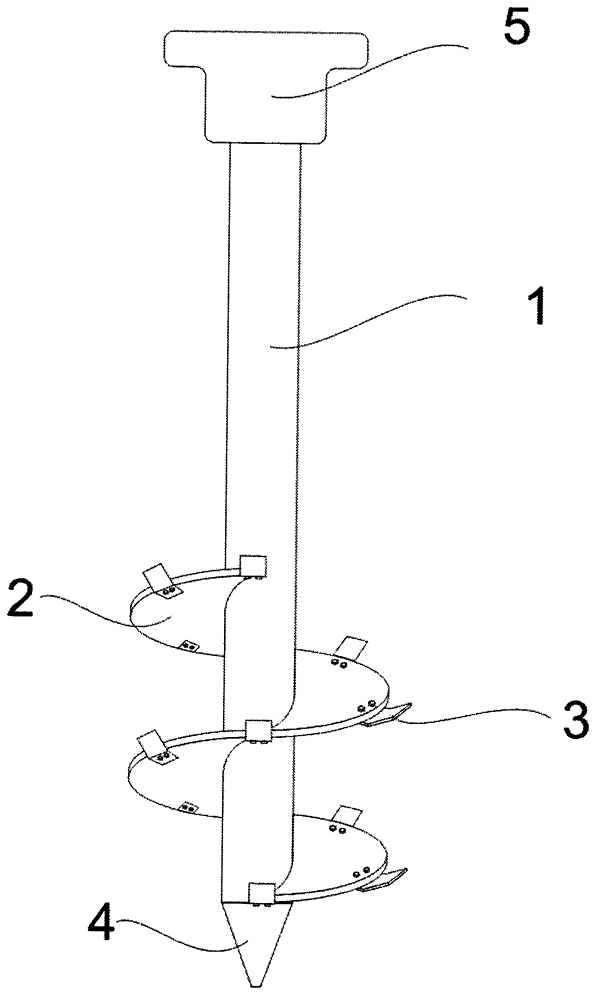
[0028] Such as figure 1 Shown is the structural diagram of the powder ridge drill bit involved in the present invention. In the figure, 1 is the screw shaft, which is made of seamless steel pipe; 2 is the screw blade, the diameter of the screw blade is 15cm, the pitch is 9cm, and the thickness of the screw blade is 5mm; 3 is the powder ridge knife, and 4 is the drill tip , 5 is a regular hexagonal flange arranged on the top of the screw shaft, and the screw blade 2 is welded on the screw shaft 1;
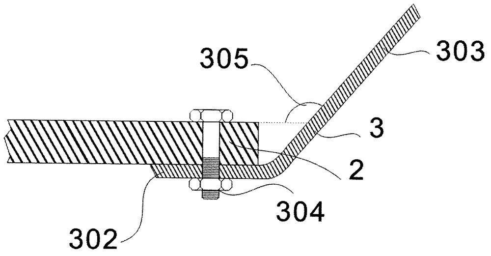
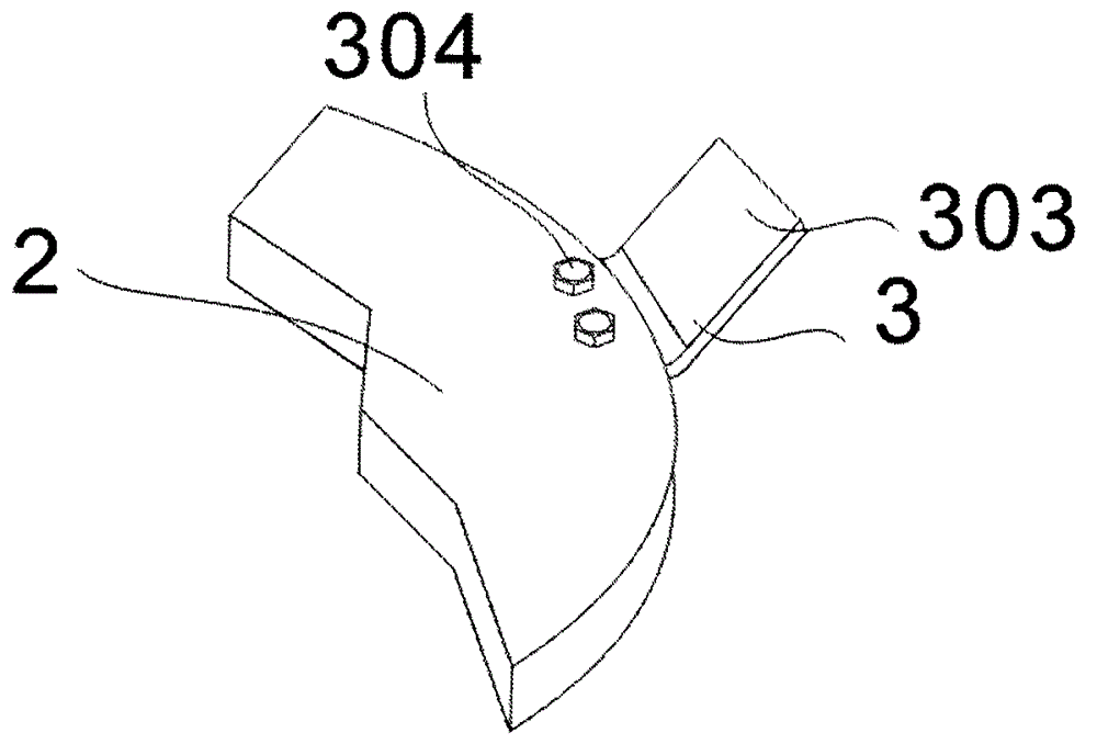
[0029] figure 2 with image 3 It is the installation structure diagram of the powder ridge knife according to Embodiment 1 of the present invention. The powder ridge knife 3 is a quadrilateral bent along the middle to form two parts: the connecting part 302 and the cutter part 303; the connecting part 302 and the cutter part 303 are roughly L-shaped, The powder ridge cutter 3 is fastened and connected to the bottom of the helical blade outer edge by bolts 304, the degree of the ...
specific Embodiment approach 2
[0032] Such as figure 1 Shown is the structural diagram of the powder ridge drill bit involved in the present invention. In the figure, 1 is the screw shaft, which is made of seamless steel pipe; 2 is the screw blade, the diameter of the screw blade is 50cm, the pitch is 30cm, and the thickness of the screw blade is 30mm; 3 is the powder ridge knife, and 4 is the drill tip , 5 is a regular hexagonal flange arranged on the top of the screw shaft, and the screw blade 2 is welded on the screw shaft 1;
[0033] Figure 4 with Figure 5 It is the installation structure diagram of the powder ridge knife according to Embodiment 2 of the present invention. The powder ridge knife 3 is a quadrilateral bent along the middle to form two parts: the connecting part 302 and the cutter part 303; the connecting part 302 and the cutter part 303 are roughly L-shaped, The powder ridge cutter 3 is fastened and connected to the top of the spiral blade outer edge by bolts 304, the degree of the d...
specific Embodiment approach 3
[0034] Such as figure 1 Shown is the structural diagram of the powder ridge drill bit involved in the present invention. In the figure 1 is the screw shaft, which is made of seamless steel pipe; 2 is the screw blade, the diameter of the screw blade is 30cm, the pitch is 20cm, and the thickness of the screw blade is 15mm; 3 is the powder ridge knife, 4 is the drill tip , 5 is a regular hexagonal flange arranged on the top of the screw shaft, and the screw blade 2 is welded on the screw shaft 1;
[0035] Image 6 with Figure 7 It is the installation structure diagram of the powder ridge knife according to Embodiment 3 of the present invention. The powder ridge knife 3 is a quadrilateral bent along the middle to form two parts: the connecting part 302 and the cutter part 303; the powder ridge knife is 40mm wide and 6mm thick, and the connecting part 302 It is roughly L-shaped with the cutter part 303, and the edge of the upper surface of the helical blade is provided with a r...
PUM
 Abstract
Description
Claims
Application Information
 - R&D
- Intellectual Property
- Life Sciences
- Materials
- Tech Scout
- Unparalleled Data Quality
- Higher Quality Content
- 60% Fewer Hallucinations
Browse by: Latest US Patents, China's latest patents, Technical Efficacy Thesaurus, Application Domain, Technology Topic, Popular Technical Reports.
© 2025 PatSnap. All rights reserved.Legal|Privacy policy|Modern Slavery Act Transparency Statement|Sitemap|About US| Contact US: help@patsnap.com