Snap fastener
一种按扣、面扣的技术,应用在日常生活领域,能够解决面扣只能重新制作、限制材料选取、无法通用产品等问题,达到有利于再生利用、减小接触面积、加快出货速度的效果
- Summary
- Abstract
- Description
- Claims
- Application Information
AI Technical Summary
Problems solved by technology
Method used
Image
Examples
Embodiment 1
[0045] Embodiment 1: Reference Figure 1 to Figure 10 .
[0046] figure 1 It shows the snap button provided by the first preferred embodiment of the present invention, which includes a face button 1 and a positioning button 2 that are fastened to each other. The positioning button 2 can be configured as a male button with a convex column structure as required, or as a The female buckle with the groove structure is not specifically limited here.
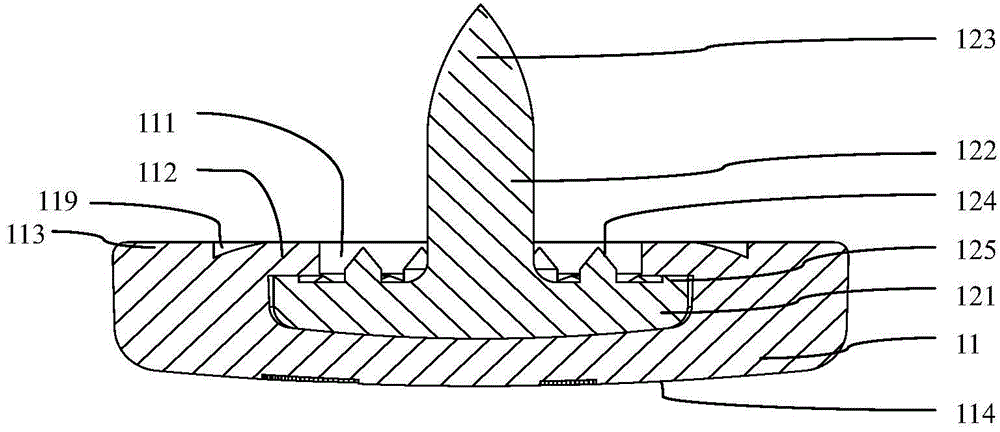
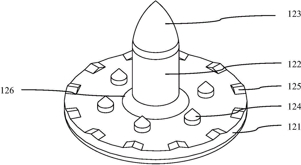
[0047]In this embodiment, the face buckle 1 includes a detachable face shell 11 and positioning spikes 12, one end of the positioning spike 12 is connected with the face shell 11, and the other end passes through the base material 3 and is connected with the positioning buckle 2, so that the face The buckle 1 and the positioning buckle 2 are respectively clamped and fixed on the base material 3 from both sides. The base material 3 can be cloth, plastic, leather, artificial leather, non-woven fabric, etc., and is often used in the m...
Embodiment 2
[0071] Embodiment two: reference Figure 11 and Figure 12 .
[0072] The face shell 11 in this embodiment is made of plastic, which is different from the first embodiment in that the face shell 11 and the positioning feet 12 in this embodiment are pressed by hot pressing. Figure 11 and Figure 12 Assemble to obtain face buckle 1's.
[0073] When installing, insert the base 121 of the positioning spike 12 downwards into the installation chamber 111 and press it against the bottom of the installation chamber 111; then, use hot pressing to deform the fixed lip 112 by heat, and move it toward the shaft 122 is bent in the direction to completely cover the anti-rotation protrusion 125, and the inner surface of the fixed lip 112 is embedded around the anti-rotation protrusion 125 to engage the concave and convex, so that the fixed lip 112 is disc-shaped and pressed against the base of the positioning foot nail 12 121. The surface of the fixed lip 112 and the anti-rotation prot...
Embodiment 3
[0076] Embodiment three: reference Figure 13 and Figure 14 .
[0077] The difference between this embodiment and the previous embodiments is that the face shell 11 in this embodiment is directly molded on the outside of the positioning spike 12 by means of injection molding.
[0078] When assembling, the produced positioning spikes 12 are placed in the injection mold, and the face shell 11 is directly covered and fixed on the base 121 of the positioning spikes 12 through injection molding. The face shell 11 after injection molding completely covers the anti-rotation protrusion 125 and engages with it, thereby preventing the positioning feet 12 from shaking or rotating in the face shell 11; The chamber 111 is exposed to prevent the surface button 1 from sliding relative to the base material 3 .
[0079] Since the face shell 11 is molded directly to form a concavo-convex structure engaging with the positioning pin 12 , the fixed lip 112 for bending to cover the anti-rotatio...
PUM
 Abstract
Description
Claims
Application Information
 - R&D
- Intellectual Property
- Life Sciences
- Materials
- Tech Scout
- Unparalleled Data Quality
- Higher Quality Content
- 60% Fewer Hallucinations
Browse by: Latest US Patents, China's latest patents, Technical Efficacy Thesaurus, Application Domain, Technology Topic, Popular Technical Reports.
© 2025 PatSnap. All rights reserved.Legal|Privacy policy|Modern Slavery Act Transparency Statement|Sitemap|About US| Contact US: help@patsnap.com


