Balloon catheter

A balloon catheter and balloon technology, applied in balloon catheters, catheters, operations, etc., can solve the problems of death of patients with myocardial infarction, stent deformation, difficulty in balloon catheters, etc., and achieve the effect of reducing risks.

Active Publication Date: 2015-04-22
孙英贤
View PDF8 Cites 6 Cited by
  • Summary
  • Abstract
  • Description
  • Claims
  • Application Information

AI Technical Summary

Problems solved by technology

However, for the post-dilation balloon catheter, since it is mainly used for post-expansion of the stent placed in the blood vessel, so that the stent can be fully opened, close to the inner surface of the blood vessel, and its passing path is basically not narrow. At present, the post-dilation balloon The tip of the balloon catheter is designed to be conical in line with the pre-dilated balloon catheter, such as Figure 1-B shown, for Figure 1-A In the partial enlarged view of part X in t

Method used


Image

  • Balloon catheter
  • Balloon catheter
  • Balloon catheter

Examples


Embodiment Construction

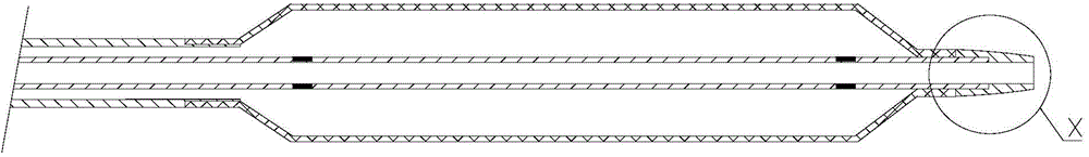
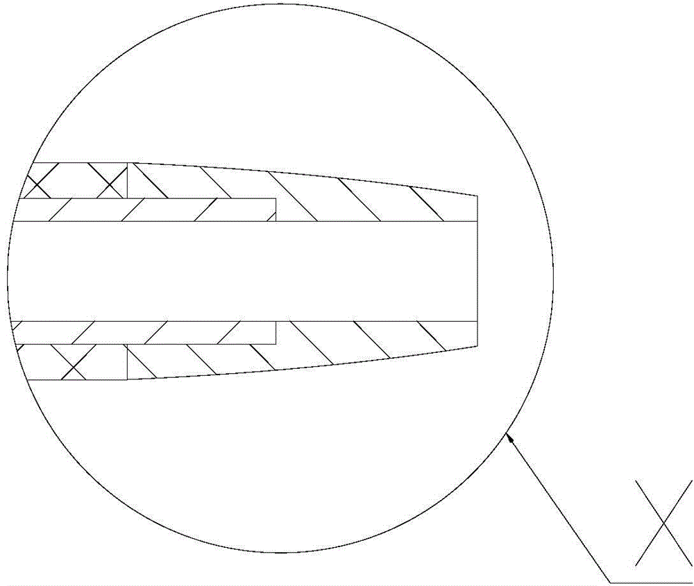
[0059] The purpose of the present invention is to provide a balloon catheter, which will not be affected by the stent mesh or the stent beam when the stent is post-expanded, so that the post-expansion process can be carried out smoothly and the occurrence of risks can be reduced.

[0060] In order to enable those skilled in the art to better understand the balloon catheter provided by the present invention, the technical solution provided by the present invention will be described in detail below in conjunction with the accompanying drawings and specific embodiments.

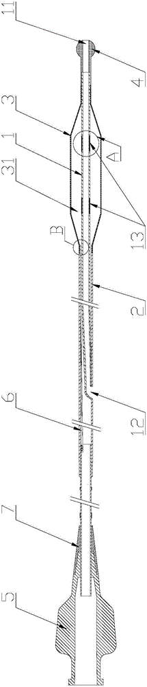
[0061] Such as figure 2 Shown is the rapid exchange (RX) type balloon catheter provided by the present invention. from figure 2 It can be seen from the figure that, in a specific embodiment, the balloon catheter provided by the present invention includes a distal inner tube 1 that runs through the inside and allows the guide wire to pass through; The distal outer tube 2; the balloon 3 that communicates with ...


PUM

PropertyMeasurementUnit
Outer diameteraaaaaaaaaa

Abstract

The invention discloses a balloon catheter which comprises a far-end inner pipe (1), a far-end outer pipe (2), a balloon (3), a joint (5) and a head end, wherein the head end is arranged at the tail end of the far-end inner pipe (1) and at least a part of the head end is a far-end swell (4); the far-end swell (4) is a bulge structure, the outer diameter of which at the swell part is greater than the diameter of the other part of the head end. The balloon catheter provided by the invention is provided with the head end with the far-end swell (4) and the bulge height of the maximum bulge position of the head end is greater than the distance between the inner edge of a bracket and the inner wall of the blood vessel, so that the head end can smoothly cross a bracket beam when entering a bracket mesh to encounter the bracket beam and the passing ability of the balloon catheter is not influenced by the bracket mesh or the bracket beam.

Description


Claims


Application Information

Patent Timeline
Owner 孙英贤
Why Eureka
Try Eureka