
Automatic water level control weir gate

A weir gate and water level technology, applied in water conservancy projects, barrage/weirs, sea area engineering, etc., can solve problems such as poor structure, easy failure, difficult installation and disassembly, etc., and achieve the effect of simple structure and sensitive response

Pending Publication Date: 2015-04-22
ONYX TIANJIN ENVIRONMENTAL PROTECTION EQUIP MFG
View PDF7 Cites 1 Cited by
  • Summary
  • Abstract
  • Description
  • Claims
  • Application Information

AI Technical Summary

Problems solved by technology

The current water level control devices include water level control gates, weir gates, flap gates, floating gates, etc. Among them, the water level control weir gate has a single form and poor structure. There are basically two types, one is the fixed water level control weir gate, and the other is the fixed water level control weir gate. This kind of weir gate is just a fixed retaining wall, and the interception length is 10 to 20 times the width of the water flow, which increases the construction cost and is difficult to maintain. Moss and scale will grow over time and it is difficult to remove. Water can only come from the weir gate. The other is the electric water level control weir gate, which works by lifting or lowering the gate, but requires gates, motors, water level sensors, drives and transmissions. Devices, etc., have complex structures, low response sensitivity, prone to failure, difficult to install and disassemble, and high construction costs

Method used


Image

  • Automatic water level control weir gate

Examples


Embodiment 1

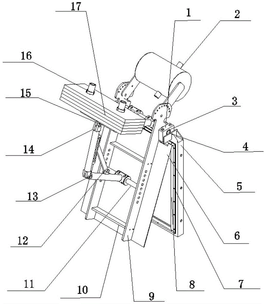
[0014] A water level automatic control weir gate, comprising a water retaining plate 6, a water retaining plate frame 9, a rotating arm assembly, a balance arm 15, a connecting rod assembly, a central arm shaft 11, a counterweight 17, a fixed frame 5, The balance water cylinder 2, the balance force arm 15 is connected on the center force arm shaft 11 by the connecting rod assembly connected in series, the center force arm shaft 11 is installed on the water retaining plate frame 9, and the water retaining plate 6 is fixed on the water retaining plate frame 9, The back reinforcement rib 10 is also inherent on the fender frame 9, and the fender frame 9 manually adjusts the angle of the balance arm 15 and the fender 6 through the connecting rod assembly, thereby changing the adjustment of the angle of the fender 6 by the impact of the water flow.

[0015] The connecting rod assembly includes a balance arm connecting rod 14 , a central moment arm connecting rod 13 and a fixed angle ...

Embodiment 2

[0019] A water level automatic control weir gate, comprising a water retaining plate 6, a water retaining plate frame 9, a rotating arm assembly, a balance arm 15, a connecting rod assembly, a central arm shaft 11, a counterweight 17, a fixed frame 5, The balance water cylinder 2, the balance force arm 15 is connected on the center force arm shaft 11 by the connecting rod assembly connected in series, the center force arm shaft 11 is installed on the water retaining plate frame 9, and the water retaining plate 6 is fixed on the water retaining plate frame 9, The back reinforcement rib 10 is also inherent on the fender frame 9. By adjusting the position of the central moment arm shaft 11 on the fender frame 9, the angle of the balance arm 15 can be adjusted, thereby changing the impact of the water flow on the angle of the fender 6. Adjustment.

[0020] The connecting rod assembly includes a balance arm connecting rod 14 , a central moment arm connecting rod 13 and a fixed angl...

Embodiment 3

[0024] A water level automatic control weir gate, comprising a water retaining plate 6, a water retaining plate frame 9, a rotating arm assembly, a balance arm 15, a connecting rod assembly, a central arm shaft 11, a counterweight 17, a fixed frame 5, The balance water cylinder 2, the balance force arm 15 is connected on the center force arm shaft 11 by the connecting rod assembly connected in series, the center force arm shaft 11 is installed on the water retaining plate frame 9, and the water retaining plate 6 is fixed on the water retaining plate frame 9, The back reinforcement rib 10 is also inherent on the water retaining plate frame 9, and the angle at which the water retaining plate 9 needs to be opened is designed according to the upstream water level, and the weight of the counterweight 17 is determined, and the counterweight 17 is fixed on the balance arm by a fastening nut 16 On 15, add water in balance water cylinder 2, add to a certain degree, make counterweight we...


PUM


Abstract

The invention provides an automatic water level control weir gate. The automatic water level control weir gate comprising a water fender, a water fender frame, a rotating force arm assembly, a balanced force arm, connecting rod assemblies, a central force arm shaft, counter weights, a fixing frame, a balanced water cylinder and a shaft seat. The balanced force arm is connected to the central force arm shaft through the connecting rod assemblies connected in series. The central force arm shaft is installed on the water fender frame. The water fender is fixed to the water fender frame. The counter weights are fixed to the balanced force arm through fastening nuts. The position of the central force arm shaft on the water fender frame is adjustable, and therefore the function of adjusting the angle of the balanced force arm is achieved. According to the automatic water level control weir gate, the angle of the weir gate can be adjusted by adjusting the weight of the counter weights so that the upstream water level of the weir gate can be adjusted; if the counter weights are different, the opening angles of the water fender are different, and therefore the purpose of controlling the water level is achieved; the function of adjusting the angle of the balanced arm can also be achieved by adjusting the position of the central force arm shaft on the water fender frame. The whole automatic water level control weir gate is simple in structure and rapid in response.

Description

technical field [0001] The invention belongs to the technical field of drainage, in particular to an automatic control weir gate capable of precisely controlling the water level. Background technique [0002] The weir gate is a gate set at the mouth of the weir to adjust the height of the weir. It is a key device for controlling a relatively stable liquid storage area. For example, it is necessary to create a relatively stable water storage area for canals, ponds, and small rivers. In the process of sewage treatment, it is necessary to create a relatively stable water storage area so that the sewage can be disinfected, sterilized, and precipitated smoothly. The current water level control devices include water level control gates, weir gates, flap gates, floating gates, etc. Among them, the water level control weir gate has a single form and poor structure. There are basically two types, one is the fixed water level control weir gate, and the other is the fixed water level c...

Claims


Application Information

Patent Timeline
Patent Type & Authority Applications(China)
IPC IPC(8): E02B7/40
CPCE02B7/40
Inventor 杨小强张学民
Owner ONYX TIANJIN ENVIRONMENTAL PROTECTION EQUIP MFG
Learn More