Combined pile supporting structure in deep and thick peat soil layer

A technology of supporting structure and peat material, which is applied in basic structure engineering, excavation, construction, etc., can solve the problems of poor hole quality of bored piles and excessive concrete filling coefficient, and achieves the solution to the problem of excessive concrete filling coefficient, high Solve the effect of poor hole quality

Active Publication Date: 2015-04-22
YUNNAN JIANTOU FOUND ENG CO LTD
View PDF6 Cites 9 Cited by
  • Summary
  • Abstract
  • Description
  • Claims
  • Application Information

AI Technical Summary

Problems solved by technology

[0003] The purpose of the present invention is to overcome the construction difficulties of bored cast-in-situ piles in deep peaty soil layers, and provide a method that can effectively solve the problem of poor hole-forming quality and concrete filling of bored cast-in-place piles in foundation pit engineering under deep peaty soil geological environments Composite pile support structure for construction problems such as too large coefficient

Method used


Image

  • Combined pile supporting structure in deep and thick peat soil layer
  • Combined pile supporting structure in deep and thick peat soil layer
  • Combined pile supporting structure in deep and thick peat soil layer

Examples


Embodiment 1

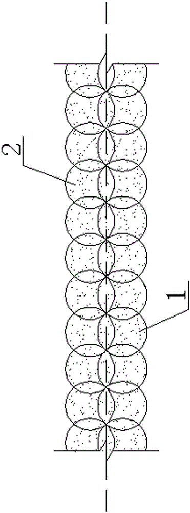
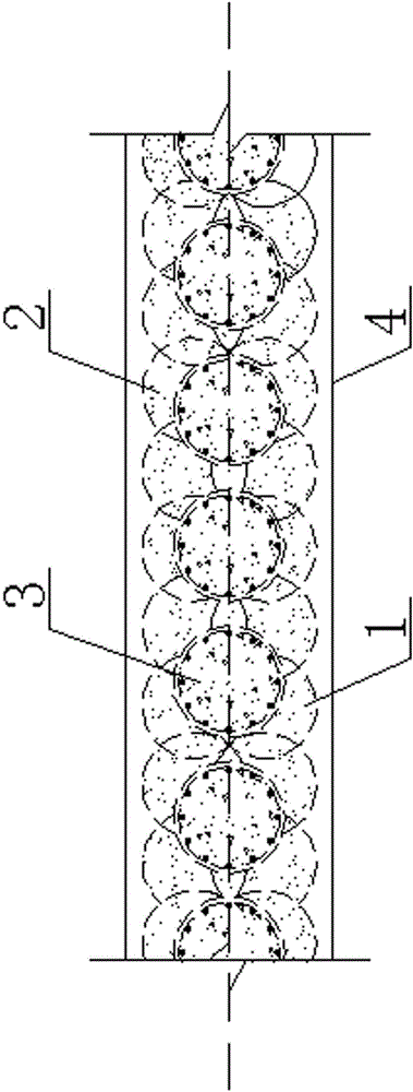
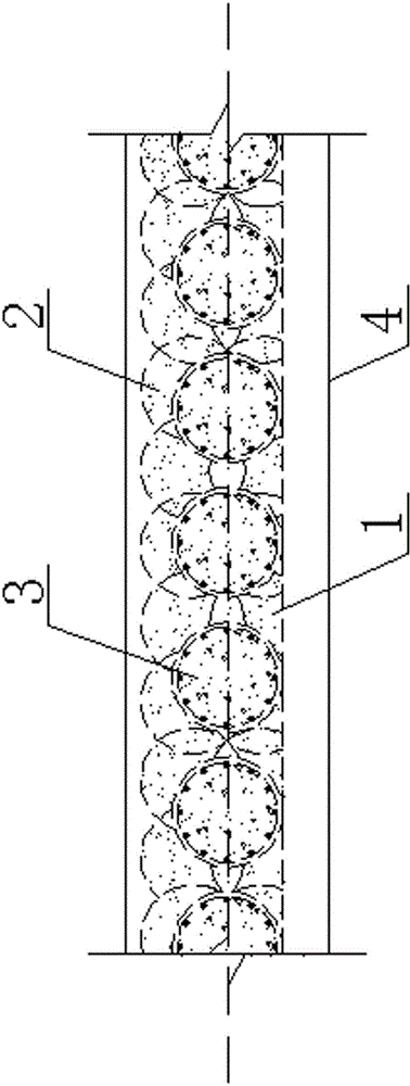
[0031] Example 1 :Such as figure 1 , 2 , 3, 4, and 6 show a combined pile support structure in a deep peaty soil layer, which consists of a front row of jet grouting piles 1, a rear row of jet grouting piles 2, bored piles 3 and crown beams 4. The design pile lengths of the front row jet grouting piles 1 and the rear row jet grouting piles 2 and the bored cast-in-place pile 3 are equal. Firstly, according to the construction axis and design pile position of the front row of rotary grouting piles 1 and the rear row of rotary grouting piles 2, the cement clay slurry with a cement dry mixing ratio of less than 8% is injected through high-pressure jet grouting (in the cement dry powder, mixed with The mixed slurry of cement and clay with content less than 8%) is used for the construction of rotary grouting piles, and the two rows of rotary grouting piles are guaranteed to interlock and be arranged in parallel to improve the engineering characteristics of peaty soil; after the p...

Embodiment 2

[0032] Example 2: Such as figure 1 , 2 , 3, 5, and 7 show a combined pile support structure in a deep peaty soil layer, which consists of a front row of jet grouting piles 1, a rear row of jet grouting piles 2, bored piles 3 and crown beams 4. The design pile lengths of the front row of jet grouting piles 1 and the back row of jet grouting piles 2 and bored piles 3 are not equal. Firstly, according to the construction axis and design pile position of the front row of rotary grouting piles 1 and the rear row of rotary grouting piles 2, inject the cement clay slurry with a cement dry mixing ratio of less than 8% through high-pressure jet grouting to carry out the construction of the rotary grouting piles, and ensure that the two Rows of jet grouted piles are interlocked and arranged in parallel to form a water-stop curtain and improve the engineering properties of peaty soil; after the pile body of the jet grouted piles tends to be stable, drill holes along the centerline of ...


PUM


Abstract

The invention discloses a combined pile supporting structure in a deep and thick peat soil layer, and belongs to the technical field of building foundation pit engineering. The combined pile supporting structure is composed of a font row of rotary jet piles, a rear row of rotary jet piles, drilling and pouring piles and a crown beam. Firstly cement clay slurry serves as grouting materials, the front row of rotary jet piles and the rear row of rotary jet piles are constructed, it is guaranteed that the two rows of rotary jet piles are arranged in a mutual-occlusion and parallel mode, a water stop curtain is formed, and the peat soil engineering features are improved; after pile bodies of the rotary jet piles tend to be stable, drilling and pouring piles are constructed along the center line of the two rows of rotary jet piles; finally the crown beam is arranged at the top ends of the three rows of piles so as to connect the front row of rotary jet piles, the rear row of rotary jet piles and the drilling and pouring piles into a whole, and the combined pile supporting structure in the deep and thick peat soil layer is formed. By means of the combined pile supporting structure, the problems that the hole-forming quality is poor and the concrete filling coefficient is excessively large when the drilling and pouring piles are constructed in the deep and thick peat soil layer can be effectively solved, the pile-forming quality of the drilling and pouring piles is guaranteed, and the engineering cost is lowered.

Description

technical field [0001] The invention relates to a composite pile support structure, in particular to a composite pile support structure in a deep peaty soil layer, and belongs to the technical field of building foundation pit engineering. Background technique [0002] With the development of the economy, urban construction continues to expand and shift from the city center to the surrounding suburbs. The available land resources in the central city area are getting smaller and smaller, and many projects must inevitably be built on soft soil foundations. The widely distributed soft soils in my country include silt, muddy soil, peat and peaty soil. At present, the research on the engineering properties of soft soil is only for silt and muddy soil, but there are not many studies on the properties of peaty soil. The engineering properties of peaty soil are poor, mainly manifested by high organic matter content, large void ratio, high water content, low natural density, high com...

Claims


Application Information

Patent Timeline
Patent Type & Authority Applications(China)
IPC IPC(8): E02D17/04
CPCE02D17/04
Inventor 秦永中郑云刚奚晶赵湖潮
Owner YUNNAN JIANTOU FOUND ENG CO LTD
Why Eureka
Try Eureka