
Construction method of high-rise building glass guardrail

A technology for high-rise buildings and construction methods, which is applied in the directions of buildings, building structures, stepped structures, etc., can solve the problems of difficult to control the accuracy and quality of on-site installation, the standardization of structural parts is not high, and the construction period of the railing system is long. Achieve the effect of easy post-maintenance and disassembly, reasonable design and short construction period on site

Active Publication Date: 2016-11-23
BEIJING HONG KONG YUAN CONSTR DECORATION ENG
View PDF6 Cites 0 Cited by
  • Summary
  • Abstract
  • Description
  • Claims
  • Application Information

AI Technical Summary

Problems solved by technology

[0002] At present, the aluminum alloy guardrail system traditionally used in high-rise buildings on the market has poor structural strength and unreliable connections. There are special requirements for grids and heights, and areas with high wind pressure values ​​cannot meet structural safety requirements.
The standardized production of the structural parts that make up the guardrail system is not high, and the accuracy and quality of on-site installation are difficult to control. The on-site construction period of the guardrail system is long, and it is not easy to replace if it is damaged later

Method used


Image

  • Construction method of high-rise building glass guardrail
  • Construction method of high-rise building glass guardrail
  • Construction method of high-rise building glass guardrail

Examples


Embodiment Construction

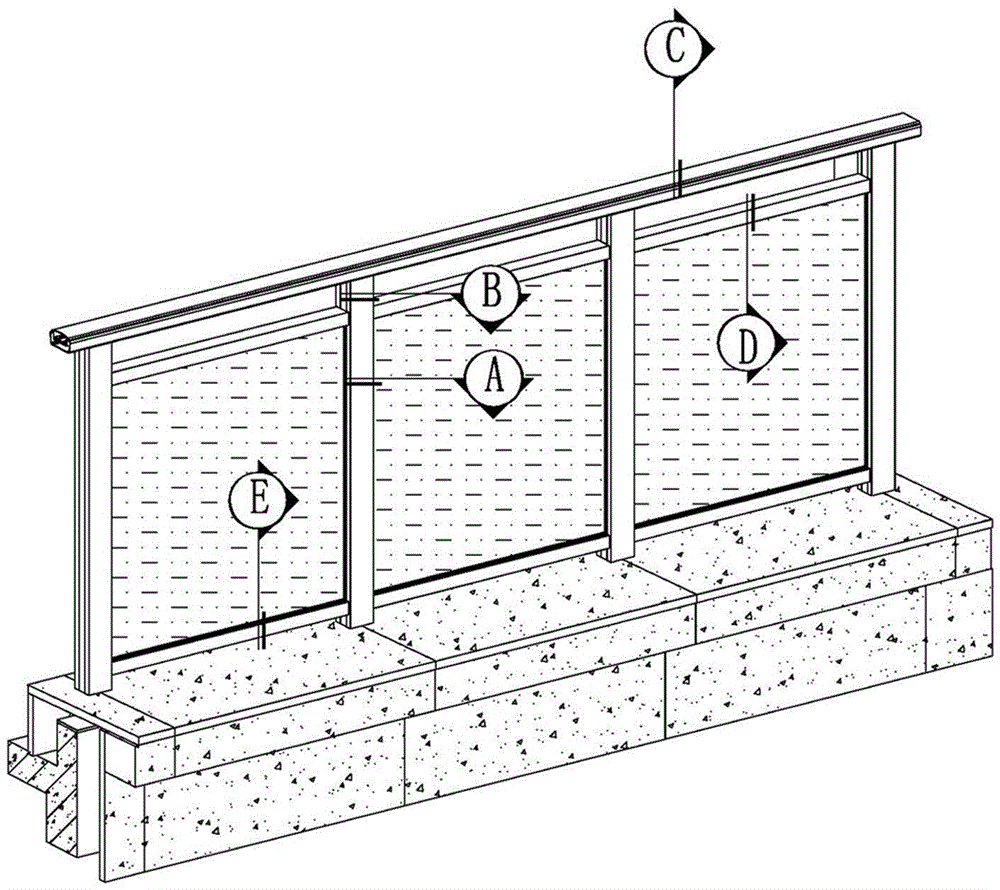
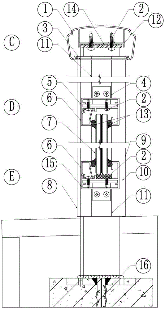
[0035] Such as figure 2 As shown, the high-rise building glass guardrail system of the present invention includes aluminum alloy corner code 4, tempered laminated glass 7, sealant and foam rod 13, self-tapping screw 2 and several pre-embedded lines arranged in the high-rise building structure Structure 16.

[0036] Such as figure 1 , figure 2 As shown, in the high-rise building glass guardrail system of the present invention, a rectangular square steel column 10 is welded on each pre-embedded structural member 16 . A handrail steel plate 12 is welded together at the tops of some connected square steel columns 10 .

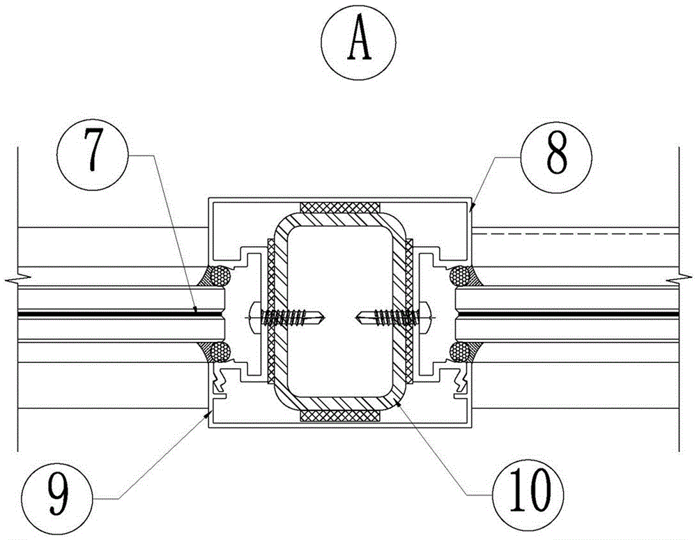
[0037] Such as figure 2 , image 3 , Figure 4 , Figure 5 , Figure 6 As shown, the rear cylindrical surface of the square steel column 10 and the cylindrical surfaces on both sides are fastened together to connect the aluminum alloy main component 8 . The aluminum alloy main component 8 is fixed on the left and right sides of the square steel column 1...


PUM


Abstract

The invention discloses a glass guardrail system for high-rise buildings and a construction method. Square steel stand columns welded to a plurality of embedded structural parts distributed evenly and connected into a line in a building structure and a handrail steel plate welded to the top ends of the square steel stand columns form a steel frame which can meet the requirement for structural safety of the area with large wind pressure. The steel frame is flexible in dimension design, so that structural safety is ensured and construction cost is reduced. Aluminum alloy main members arranged on the outer side of the steel frame and vertical column buckle plates are of split locked lid combination structures, and aluminum alloy guardrail handrails and handrail buckle plates are of split locked lid combination structures, so that assembly and disassembly are facilitated. An upper cross beam, a lower cross beam and the aluminum alloy main members are connected through aluminum alloy connectors, so that field installation is convenient, and connection quality is ensured. Tampered and laminated glass is arranged on the upper cross beam and the lower cross beam through cross beam buckle strips, so that broken glass can be replaced easily. The glass guardrail system is used for high-rise steps or the peripheries of observation decks of the high-rise buildings. The glass guardrail system is reasonable in design, simple in installation, high in precision and quality, and short in construction period, the members are produced in a standard mode according to a drawing, and later-period maintenance and member replacement are easy.

Description

technical field [0001] The invention relates to a construction method of a guardrail of a building, in particular to a construction method of a glass guardrail of a high-rise building. Background technique [0002] At present, the aluminum alloy guardrail system traditionally used in high-rise buildings on the market has poor structural strength and unreliable connections. There are special requirements for grids and heights, and areas with high wind pressure values ​​cannot meet structural safety. The standardized production of the structural parts that make up the guardrail system is not high, and the accuracy and quality of on-site installation are difficult to control. The on-site construction period of the guardrail system is long, and it is not easy to replace if it is damaged later. Contents of the invention [0003] An object of the present invention is to provide a construction method for a high-rise building glass guardrail system with unified model and standardi...

Claims


Application Information

Patent Timeline
Patent Type & Authority Patents(China)
IPC IPC(8): E04F11/18
Inventor 吴治刚耿雷韩冰邹继武许昌得
Owner BEIJING HONG KONG YUAN CONSTR DECORATION ENG
Learn More