Method for measuring gas well critical liquid-carrying flow

A technology of liquid-carrying flow and gas well, which is used in surveying, earth-moving drilling and production, wellbore/well components, etc., can solve problems such as inability to meet the actual situation in the field, and achieve the effect of reliable principle

Inactive Publication Date: 2015-04-22
PETROCHINA CO LTD
View PDF5 Cites 13 Cited by
  • Summary
  • Abstract
  • Description
  • Claims
  • Application Information

AI Technical Summary

Problems solved by technology

[0006] The purpose of the present invention is to solve the problem that the calculation of the critical liquid-carrying flow rate similar to the Sulige gas field by using the existing critical liquid-carrying flow model obviously cannot meet the actual problem on site

Method used


Image

  • Method for measuring gas well critical liquid-carrying flow
  • Method for measuring gas well critical liquid-carrying flow
  • Method for measuring gas well critical liquid-carrying flow

Examples


Embodiment 1

[0027] This embodiment provides a method for measuring the critical liquid-carrying flow rate of a gas well, including the following steps:

[0028] Step 1: Check the well history data of the gas well to obtain the tubing diameter D; take the gas from the gas well, measure the gas composition, and then calculate the relative density γ of the gas relative to the air;

[0029] The relative density γ is obtained by the following method:

[0030] (1) Obtain the gas in the gas well and test its composition;

[0031] (2) Obtain the average relative molecular mass according to the relative molecular mass of each component;

[0032] (3) Calculate the relative density γ from the ratio of the average relative molecular weight to the molecular weight of air.

[0033] Step 2: Measure the bottom hole pressure and temperature T, according to bottomhole pressure and temperature T using an iterative method to calculate the corresponding compression factor ;

[0034] bottom hole press...

Embodiment 2

[0046] Derivation of the present invention: according to the algorithm of Guo and Ghalambor, the kinetic energy factor reflects the flow characteristics of the gas-water two-phase in the tubing. The primary controlling factor for fluid accumulation is downhole conditions. The kinetic energy factor E at the tubing shoe is used as the basis for evaluating the liquid-carrying capacity of gas wells.

[0047]

[0048] (1)

[0049] It can be solved by formula (1):

[0050] (2)

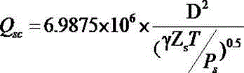
[0051] In the formula: ——the flow velocity of the gas at the tubing shoe, m· ;

[0052] ——The density of the gas converted to the tubing shoe, kg· ;

[0053] Q - gas production, · ;

[0054] γ——gas relative density;

[0055] T——downhole temperature, K;

[0056] Ps ——flow pressure at the tubing shoe, MPa;

[0057] D — diameter of oil pipe, m;

[0058] Zs——compressibility factor of ...

Embodiment 3

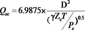
[0073] A well carried out a flow pressure test on October 19, 2013, and its test output was 0.9794×10⁴ / d, the bottomhole flowing pressure is 10.98MPa, the temperature is 378.2K, the relative density of natural gas is 0.6, and the compression factor is 0.93. Substitute the above data into the formula:

[0074]

[0075] The calculated minimum liquid-carrying flow rate of the well is 0.5995×10⁴ / d, less than the actual output 0.9794×10⁴ / d, able to carry liquid production, according to statistics, the daily liquid production of the well is 0.18 , the analysis results are consistent with the actual situation.


PUM


Abstract

The invention belongs to the technical field of gas production technologies in oil and gas fields, and particular relates to a method for measuring gas well critical liquid-carrying flow. The method includes the steps that gas well history data are searched for to obtain the oil pipe diameter D; gas well gas is sampled to measure gas components, and then the relative density gamma of the gas relative to air is calculated; bottom hole pressure Pm and temperature T are measured, and a corresponding compressibility factor is calculated through a iterative method according to the bottom hole pressure Pm and the temperature T; the critical liquid-carrying flow is calculated by using the oil pipe diameter D, the relative density gamma of the gas, the pressure Pm, the temperature T and the corresponding compressibility factor. According to the method for measuring the gas well critical liquid-carrying flow, a kinetic energy factor is cited and combined with practical production data of a Sulige gas field to determine a critical liquid-carrying flow formula, and a simpler and more reliable method is provided for determining the critical liquid-carrying flow of the Sulige gas field. The principle is reliable, and compared with an existing critical liquid-carrying flow model, the method fits the practical situation of the Sulige gas field better.

Description

technical field [0001] The invention belongs to the technical field of gas recovery technology in oil and gas fields, and in particular relates to a method for measuring the critical liquid-carrying flow rate of a gas well. Background technique [0002] When the gas well is in normal production, the gas is the continuous phase, the liquid is the dispersed particles, and the liquid is carried to the ground by the gas in the form of particles, but when the flow rate of the gas decreases, its carrying capacity will decrease. The energy in the wellbore makes the fluid in the wellbore flow out of the wellhead continuously, so that the liquid will accumulate at the bottom of the well and form effusion. In order to ensure that the gas well does not accumulate liquid, the production of the gas well must be greater than the critical liquid-carrying flow rate. Therefore, the critical liquid-carrying flow rate of the gas well is a very important data. [0003] Scholars from various co...

Claims


Application Information

Patent Timeline
Patent Type & Authority Applications(China)
IPC IPC(8): E21B47/00E21B49/08G06F19/00
CPCE21B47/00E21B49/08E21B49/0875G16Z99/00
Inventor 韩兴刚马海宾李进步冯朋鑫徐文龙王晓荣王宪文张春雨赖海涛高仕举茹志娟梁倚维杨向东
Owner PETROCHINA CO LTD
Why Eureka
Try Eureka