
Mining intrinsically safe multi-point displacement meter

An intrinsically safe, displacement meter technology, applied in the direction of using electrical devices, electromagnetic means, construction, etc., can solve the problems of easy winding and complicated installation.

Active Publication Date: 2015-04-22
晋能控股电力集团有限公司 +1
View PDF14 Cites 17 Cited by
  • Summary
  • Abstract
  • Description
  • Claims
  • Application Information

AI Technical Summary

Problems solved by technology

[0003] The purpose of the present invention is to overcome the above-mentioned shortcomings, provide a method to reduce the number of multi-point displacement measuring ropes in the same borehole in the mine roadway roof rock layer, and effectively solve the complicated installation and easy entanglement of multi-point displacement and multiple measuring ropes in the same borehole Mine Intrinsically Safe Multipoint Displacement Meter

Method used


Image

  • Mining intrinsically safe multi-point displacement meter
  • Mining intrinsically safe multi-point displacement meter
  • Mining intrinsically safe multi-point displacement meter

Examples


Embodiment 1

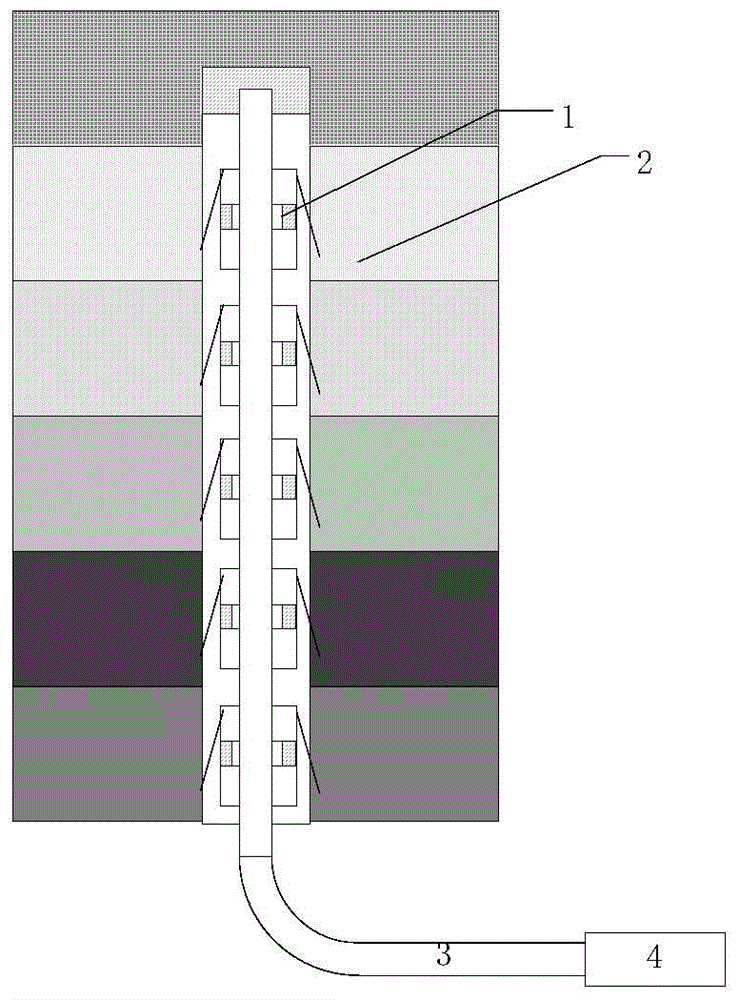
[0030] A mine 3 #The coal seam exposes a goaf in the 320m material transportation roadway that has been constructed. The goaf is 38m long, 15m wide, and about 3.5-4m high, and the gobs in the middle are staggered. The present invention is used to monitor the displacement of 5 rock layers such as the roof mudstone layer, argillaceous sandstone layer, fine sandstone layer, mud-sandstone interbed and mudstone layer in the two mined-out areas of the material transportation roadway. The same drilling diameter of the roof rock layer is 28mm, and The structure consists of 5 magnetic anchor heads, 1 flexible measuring rod, instrument cabin, echo transduction detection device, magnetostrictive wire support block and end point fixing device, among which 5 magnetic anchor heads are respectively anchored in the material transportation aisle There are 5 rock formations on the roof of the two goafs, including mudstone layer, muddy sandstone layer, fine sandstone layer, muddy sandstone inter...

Embodiment 2

[0034] A mine 3 # Coal seam 1 mining area 3101 working face encounters a goaf at 20m away from the return air trough, which is a gob roadway with a width of about 16m and an unknown length. The displacement of two rock formations, the direct roof and the basic roof of the roof of the goaf, is monitored by the present invention. The diameter of the same drill hole in the roof rock layer is 28mm, and its structure consists of two magnetic anchor heads, which are respectively anchored to the two rock layers on the direct top and basic top of the roof in the empty area, with relative displacements of 43mm and 17mm. The actual multi-point displacement monitoring effect is good. Others are with embodiment 1.


PUM


Abstract

The invention discloses a mining intrinsically safe multi-point displacement meter with magnetic anchor heads and a magnetostrictive line as displacement sensors. The mining intrinsically safe multi-point displacement meter is structurally composed of the magnetic anchor heads, a flexible measuring bar, an instrument cabin, an echo energy change detection device, magnetostrictive line supporting blocks and an end fixing device, the magnetostrictive line is arranged in the flexible measuring bar, the magnetic anchor heads are fixed to a mine tunnel roof rock layer, a processor sends an electric pulse to the magnetostrictive line through a drive circuit, the electric pulse and the magnetic anchor heads interact to form torsional waves and longitudinal waves, the electric pulse spreads in the magnetostrictive line, the arrival time of an echo wave is detected through the echo energy change detection device, and the roof displacement of the positions of the magnetic anchor heads can be calculated. Compared with a multi-point displacement meter with four to six measuring ropes, the number of multi-point displacement ropes in the same drilled hole of the mine tunnel roof rock layer can be reduced, and the problem that the multi-point displacement ropes in the same drilled hole are complex in mounting and prone to being wound is effectively solved.

Description

technical field [0001] The invention belongs to the technical category of the displacement monitoring of the roof rock layer of the mine roadway in the coal measure formation, and specifically relates to a mining intrinsically safe multi-point displacement meter using a magnetic anchor head and a magnetostrictive wire as displacement sensors. Background technique [0002] Mine roadway roof displacement monitoring instruments are mainly divided into two types: (1) Roof delamination instrument, there are two base points for delamination monitoring, namely deep base point and shallow base point, consisting of deep base point anchor head, shallow base point anchor head and two measuring The rope forms the roof displacement measurement sensor, such as the disclosed roof sinking and separation layer indicator (CN2384212), surrounding rock separation layer monitoring instrument (CN300727230), surrounding rock separation layer monitoring and alarm instrument (CN2688894), multi-direct...

Claims


Application Information

Patent Timeline
Patent Type & Authority Applications(China)
IPC IPC(8): E21B47/13G01B21/02
CPCG01B7/02
Inventor 王东李风珍何小刚鲁伟邵祥朱跃琴倪嘉贾存华韩浩李忠福李亚君王玉玲
Owner 晋能控股电力集团有限公司
Learn More