Gas turbine rotor disc seam positioning structure and gas turbine rotor

A gas turbine and positioning structure technology, which is applied to machines/engines, mechanical equipment, engine components, etc., can solve problems such as high cost and reduced structural durability, and achieve the effects of reducing extrusion stress, reducing requirements and facilitating assembly.

Active Publication Date: 2017-01-11
BEIJING HUAQING GAS TURBINE & INTEGRATED GASIFICATION COMBINED CYCLE ENG TECH
View PDF4 Cites 2 Cited by
  • Summary
  • Abstract
  • Description
  • Claims
  • Application Information

AI Technical Summary

Problems solved by technology

In addition, the rotor mounting structure of the prior art sometimes even leads to a reduction in the durability of the structure, requiring the use of high-strength materials or thickening the thickness of the wheel disc or even developing a new assembly process, which has the problem of causing high cost

Method used


Image

  • Gas turbine rotor disc seam positioning structure and gas turbine rotor
  • Gas turbine rotor disc seam positioning structure and gas turbine rotor
  • Gas turbine rotor disc seam positioning structure and gas turbine rotor

Examples


Embodiment Construction

[0023] The specific implementation manners of the present invention will be further described in detail below in conjunction with the accompanying drawings and embodiments. The following examples are used to illustrate the present invention, but are not intended to limit the scope of the present invention.

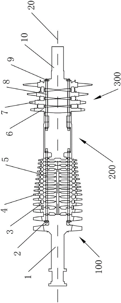
[0024] figure 1 It is a structural schematic diagram of a gas turbine rotor, which includes three parts from front to back: a compressor rotor unit 100 on the compressor side, an intermediate shaft 200 and a turbine rotor unit 300 on the turbine side. The compressor rotor unit includes a compressor shaft head 1 , a compressor wheel 3 , and a circle of circumferentially spaced compressor blades 4 mounted on the compressor wheel 3 , a compressor tie rod 5 and a compressor tie rod nut 2 . The compressor motor blade 4 is arranged on the outside of the compressor wheel 3, and can compress air to perform work under the drive of the compressor wheel 3. Adjacent compressor discs...


PUM


Abstract

The invention relates to the field of gas turbine rotors and discloses a wheel disc spigot locating structure of the gas turbine rotor and the gas turbine rotor. Two wheel discs are axially overlapped, axial bumps are arranged at the opposite head faces of the two wheel discs, axial grooves are formed in the other head faces, and the outer diameters of the axial bumps are in interference fit with the inner diameters of the axial grooves; each axial bump is provided with an interference amount adjusting nick; the interference amount adjusting nick is a circular ring-shaped nick formed in the axial head face of the axial bump. By means of the wheel disc spigot locating structure, the wheel disc of the rotor can use a small interference magnitude when assembling, the device extrusion stress is reduced, the assembly is facilitated, the requirement on fixture is lowered, the rotor fits tightly under a working state, and the gas turbine rotor integrity is guaranteed.

Description

technical field [0001] The invention relates to the field of gas turbine rotors, in particular to a gas turbine rotor disc stop positioning structure and the gas turbine rotor. Background technique [0002] The gas turbine rotor includes a section on the compressor side, a section on the turbine side, and an intermediate shaft connecting the two sections. Both sections include multi-stage disks, and the adjacent two disks of the multi-stage disk The end faces are mated. An axial protrusion is processed on one end surface of two adjacent discs, and an axial groove is processed on the opposite end surface thereof, and the axial protrusion is inserted into the axial groove to form a notch positioning fit. The installation and cooperation of the axial protrusion and the axial groove need to have strict coaxiality requirements. [0003] In order to meet the radial and axial positioning requirements, when the discs of the gas turbine rotor are assembled at all levels, the positi...

Claims


Application Information

Patent Timeline
Patent Type & Authority Patents(China)
IPC IPC(8): F01D5/06
Inventor 陈海燕冯泽军刘丙权李炳涛
Owner BEIJING HUAQING GAS TURBINE & INTEGRATED GASIFICATION COMBINED CYCLE ENG TECH
Why Eureka
Try Eureka